cam-eleon
-
Posts
91 -
Joined
-
Last visited
-
Days Won
2
Content Type
Profiles
Forums
Downloads
Store
eMastercam Wiki
Blogs
Gallery
Events
Everything posted by cam-eleon
-
Try using 3D tool type set to Multi-function for your drill
-
How about rotary hex broaching...... http://www.slatertools.com/ there could be more but I don't know too much about it. Or just run a hex punch
-
I feel your frustration. The problem is a plot issue and more importantly the posted code. Your machine moves 45 deg. I don't know if you can change parameters to have the machine rapid different. The sure way is to have the post set to fast feed (ex G01 F400ipm) for rapid motion. Not what you want to hear. I think todays machines move axis at different feeds while in rapid to create a straight line as opposed to old time dog leg fashion.
-
Pocket Toolpaths Still Run Through a Boss, After All These Years
cam-eleon replied to Jobnt's topic in Industrial Forum
I just hit re-gen in 2023 and it goes around the island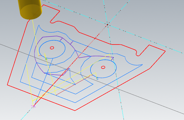
-
select the target body

-
can't open pdf files in mastercam 2023
cam-eleon replied to [email protected]'s topic in Industrial Forum
Some PDF's are just images/scan/pictures. I had this happen to me. But the PDF import works. Just double check the scale factor when in comes in. -
I've programmed VTL's way back in the day. I would just program the part like a conventional cnc horizontal lathe, in the upper quad, like normal. In actuality the control flips/mirrors the normal cnc lathe program over to the operators side of the part on the VTL. It won't change the std G03/G02 direction. This was way my machine was set up. So I would have to imagine the tool running on the other side of the vertical centerline to do any at the machine edits. It was a bit confusing.
-
Change the lock value to lock it in at your initial 20.001 deg if that works for you. Or 70.001 or 69.999 what ever....
-
I've had slight unexpected drifting of rotary axis in the past. No with your exact toolpath. I would resolve it by locking in the angle with my limits. try the axis lock in the toolpath. You have to turn on (check) "limits" in tool axis control in order to set limits. I would try that first. Enter 20 and 20 or what ever the value is. You don't have to have a range. That's what I used to do.
-
Broke the cutter with Line/Arc filtering
cam-eleon replied to Shiva.aero's topic in Industrial Forum
It would be interesting to run the linear vs the arc filter programs through Vericut Force. It may capture the spikes that break the cutter... -
Ignore pockets smaller than setting??? I'm totally guessing here...
-
https://www.machiningdoctor.com/calculators/chip-thinning-calculator/ here is a site that will give factoring for radial and axial chip thinning. The axial factoring take into account ball and button tools based on DOC as well as "lead angle" of cutting edge (ie) high feed cutters. I just came across this site so look it over to see if it's suitable for your needs. It does give a good examples and explanations. I have the app from this site but to me it's not comprehensive enough.
-
-
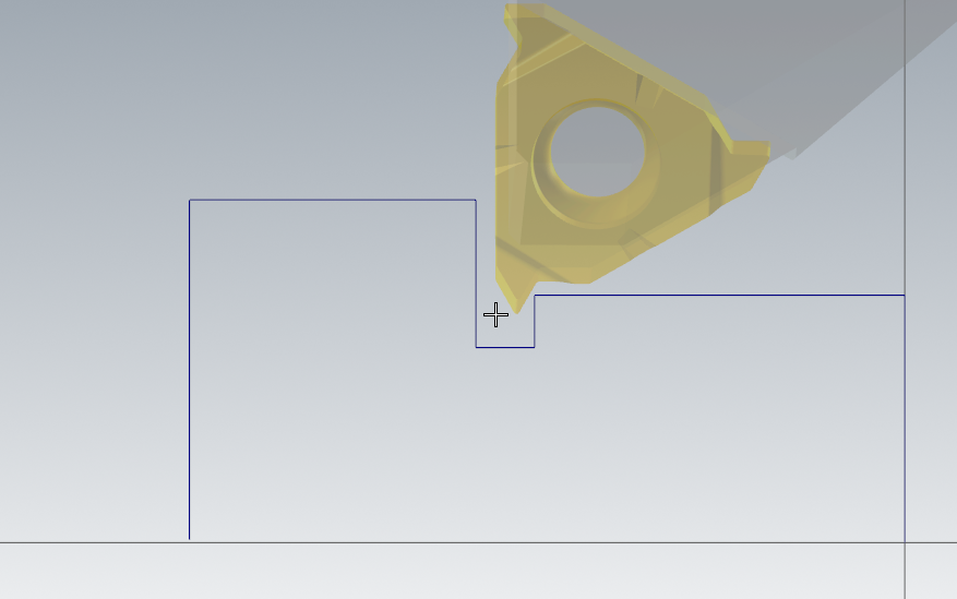
Yep I had the same issues. I think I just ended up defining a custom tool with the comp point at the leading face of the insert. Not that this solves your issue but making a 3D tool at the front of the insert seems possible.
-
Would this be for a twin screw pump? I am very familiar with this type of component if that's what it is. I used a mazak Integrex machine. Sorry but my French is not non existent
-
Try File, Repair maybe...
-
No, but it end up that way till I figured what the heck I was doing
-
My first 4ax wire test was my first initial at the top and my 2nd initial at the bottom.
-
I guess I cheat a bit and assemble the insert with the holder in Mastercam design session and then save the model already assembled and paired up, insert in position. Then I use that model in my 3D tool. You don't have to worry about using the 3D tool insert mating methods.
-
I'm old school. Sketch in every rough pass with a ramp type 2 d contour if you have to. Then all arcs are/should be in the top view. Worry about the last pass/passes as a 3d cut. Then the boss is off your back.....
-
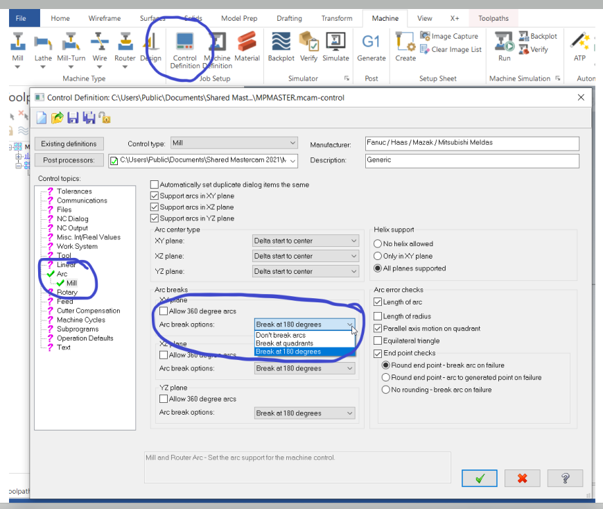
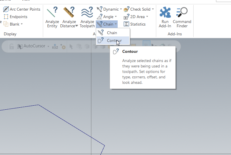
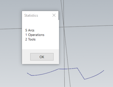
From what I know machines will only execute proper helical code on arcs in the G17 plane. Helical code is a G02/3 with a linear Z motion. Circles on the G18, G19 plane by definition will contain a Z. There are 5 arcs in the chain. If you close each arc and don't see a perfect circle as viewed from the top,front, or right/left then there are no G17,18,19 arcs.
-
Only a couple of the arcs are on the xy, yz, xz planes. You won't be able to filter/create arcs on circles that are not on the G17, 18, 19 planes
-
I think you are already at the XY positions of the skipped arc move. So it would need to be a 360deg arc?? If that's OK then split the move into 2 G03 moves
-
I looking very quickly at this now. I'm a bit old school but I would define a new stock model before your OP5. I sometimes have my very first op as a stock model. I also have 2-3-4 stock models as I go along and then refer to the last stock model as my current part condition for my rest milling op.