


White Feather
-
Posts
11 -
Joined
-
Last visited
White Feather's Achievements
")
Newbie (1/14)
1
Reputation
-
Just out of curiosity what would be the amount of programmers required on a per machine basis in an average aerospace job shop which does no more than say 20% repeat work; which of course means that 80% of the work will need to be processed and programmed from scratch. In this scenario lets say the programmers duties would be creation of all the required CNC programming/verification, solid modeling if needed, fixtures/work holding, tooling selection, as well as material size selection. The programmer would of course also interface with the machinist/operator on the floor for setup/operation, and any required editing or changes in the process. Lets assume this is just a typical small/medium job shop, average sized machines, no gantry work or big VTL stuff... just for example lets say the equipment is as below.. 20% of the machines are typical 3+1 mills at @40" of X travel... think Mazak 510/Haas VF4SS. 15% of the machines are small palletized 4 axis horizontal mills... think Makino A51/Mitsui Vertex. 15% are mill turns with average sized swing... think Mazak 250MY/Okuma Crown. 20% are multitasking machines... think Mazak i200 Integrex/Mori NTX. 20% are average sized 5 axis mills... think Mazak i600 Variaxis/DMG/DMU. 5% are larger 4 axis palletized horizontal mills, think Mazak 8800 or Mitsui HS6a. 5% are larger vertical multitasking, think Mazak i630 integrex/Mazak i1050 integrex. Assume a normal mix of material types, complexity of components, and dimensional tolerancing for typical aerospace applications. I realize this is a very generalized broad question which requires a coat of paint with a very very wide paintbrush; I myself have worked on several components over the years that required every bit of my time on a single piece for months.... but for the sake of this argument just exclude that type of job as a possibility. I'm not looking for exact numbers just a generalized idea of what you opinions are, a high/low answer is fine and any answer is appreciated. Thanks!
-
That's kind of my train of thought on it as well, but since I have absolutely no experience with it I figured it best to at least ask. Even if we did decide to try and use it I would never be doing it myself, I strictly program our bigger more complex stuff... we have a few other programmers who do everything else in another building... all of our small stuff is in one building and the big stuff is in mine.
-
My boss wanted me to find out if it is actually feasible for us to use the FBM feature on simpler small vise sized 3 axis milling parts... I've never used it for anything at all as most of the stuff I work on is larger 5 axis work so I have no idea of its capabilities/limitations, but I'm rather skeptical about it. We don't do any production work, 90% of our work is aerospace and generally only 1-4 parts so we aren't really worried about making things run as aggressively as you would a production job, but some of the parts are a little complex for their size and require some 3d work occasionally... I'd provide and example but most of the parts are ITAR. Opinions? Any help appreciated.
-
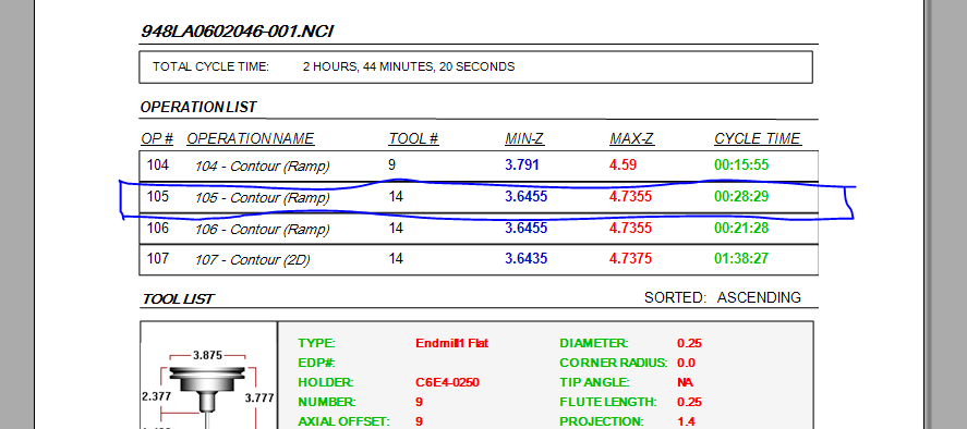
I have an edited setup sheet template that I like but I'd like to make one change and I'm kind of lost trying to do it even though it should be super simple.. What I want is to add a blank block under each toolpath in the operation list when the setup sheet is generated so the operator could add notes for each toolpath... looking at the picture attached imagine a blank square block between op104, op105, op106, etc etc where I drew in the lines... I did all my own editing on all the rest of my setup sheet template with no problems.. but for some reason I can't get this one to work. Thanks!
-
I need to order my new graphics cards today... I'm looking at the Nvidia quadro.... M2000, M4000, P4000, and the K4000.... I've been running the M4000 in my old workstation and it seems to do OK, I have another workstation with 2 M2000 cards and it seems to do better than the single M4000. Any opinions? I'm specifically running Mastercam, Catia and solidworks mainly, and usually driving 4 monitors. This Is in a dell 7600 w dual E5-2687w processors fwiw. Thanks
-
Got it.. Thanks! Settings. Configuration. Files... Number of files folders to display in MRU fields. Somehow I was overlooking that.
-
I just setup a new workstation.. I remember somewhere you can change the number of files in the file history to a max of 20... where was this option located? I'll be darned if I can find it. Thanks!
-
I don't actually remember file size or how many lines of code... but once upon a time I did a lot of stuff for a 5 axis gantry which was approx. 60ft long in X and prolly 20 ft long in Y.. these were large panels for the SLS fuselage mostly 3 axis but with some fine detail work in 5 axis as well as 3d work with fine finish. The larger of the files would take an hour or better to post in Catia, and the vericut sims I would leave running overnight and into the next day. I loved those parts.. post out a roughing program and let it run for weeks at a time.
-
Something I have done on occasion to get around this issue... Probably not the best solution, but it does work. testing.mcx-9
-

Saving stock model to different format
White Feather replied to White Feather's topic in Industrial Forum
That's about what I figured.. I was just hoping there was a magic trick I wasn't aware of. I'll just give him some wireframe to use for his alignment, that's not really a big deal.. it would just be nice to have a solid of the actual material condition between ops so that he can program offline and then not run into unexpected surfaces. He might be able to do this off the .stl but he doesn't know how to make it happen; I'll check on this and see if I can help him out... having time to actually make a solid would be problematic most of the time. Thanks. -
White Feather changed their profile photo
-
Where I'm at we build a lot of thinwalled airframe components such as cowling pieces and fuselage pieces out of large-ish chunks of billet... these are almost always comprised of 100% radi either true 5 axis or in many cases completely 3d machined these parts rarely have any straight edges and many of them don't have any holes or any other features. I'm normally machining these off of holding tabs using a subplate and locating with dowel pins in a few of the holding tabs which will be mown off on the last op. These parts can be tricky to get a good alignment on the CMM, I'd like to be able to provide the CMM programmer with an in process stock model similar to the STL file you get by saving the verification stock.. this would allow him to create his initial alignment from the dowel pin holes used for fixturing.. the only issue with this is he can't do anything with an STL file.. Is there an easy way to save this file as a .stp? I've tried opening the .stl then save some or save as a .stp file but it never works.. What I have to work with is Mastercam, Autodesk Inventor (I am clueless with Inventor) and the Calypso DMIS software. Any help greatly appreciated.
