


Manofwar
-
Posts
106 -
Joined
-
Last visited
-
Days Won
2
Content Type
Profiles
Forums
Downloads
Store
eMastercam Wiki
Blogs
Gallery
Events
Posts posted by Manofwar
-
-
Something to note with the approach you're looking at. It's going to create a lot of straw like chips in the part that will be very hard to remove with flood coolant. If you have it use TSC, chip clearing can be a real nightmare on cavity work in Ti.
-
 1
1
-
-
I use Sublime Text, which would be able to do this. It would take some programming knowledge, but shouldn't be to much of a hassle.
It's also free and open source.
-
1
-
-
Something else, be very careful making threads in this material. You can tap it, but it requires tapping fluid, and peck tapping most of the time. It's generally a lot safer to threadmill, if you only have a couple parts to make, I would suggest it over trying to figure out tapping. (unless you have a sacrificial piece to figure out how the tapping works.)
-
 1
1
-
2
-
-
Something of note when working with S class materials. Be very careful about your first passes against raw stock. If the stock is oversized you can over engage your tool. Which will break the tool instantaneously. I generally always drew my stock .02"-.05" larger then what I measured to help with this issue. The material wants to soak heat, even blipping the coolant off for a second while it's touching material can end the tools life. If you have TSC use it!
-
1
-
1
-
-
Check all fluids. Had a similar issue once on a Mazak I300 with a smooth control where the fluid had just gotten low on the thermal compensation tank.
-
Do a search for "DPAS rating chart" you should come up with a .pdf made by DCMA. Almost everything everyone has posted falls under this document, which lines up with the verbiage you're using.
"Title 1 of the Defense Production Act (DPA) of 1950 is the statutory basis for the Defense Priorities and Allocations System (DPAS). Title 1 is also one of the non-permanent provisions of the DPA that needs to be periodically reauthorized, which Congress has done in the past for periods of 1 to 5 years. The DPA provides the President with the authority to require acceptance and priority performance on contracts and orders, and to allocate materials, services, and facilities to support national defense and emergency preparedness requirements. The President has delegated his priority and allocation authority to the Department of Defense, the Department of Homeland Security, and the Department of Energy according to resource required."
As you can see from the above excerpt, they can do a lot more then force you to start making a part you bid/won on. They can force historic parts on you if they can't source them from another shop(s) for some reason. DO and DX are ratings that fall under DPAS, with sub categories for different types of equipment under them.
The person you talked to previously was most likely referring to a sub category under the DPAS umbrella.
Hopefully the document provides some clarity.
-
1
-
-
DPAS rating is probably what you're looking for.
-
1
-
3
-
-
@Slick Not using MC for this. Running another CAM software at the moment. Time to run was about 6 minutes. I know from previous experience that Mastercam was pretty good with times. If you removed tool changes and other ancillary actions from the machine, the time would be about +-5% of the predicted time. (At least for the machines and posts I was using.) This would change significantly for the 5 axis paths if you were running something not COR as the machine would have much further to travel for each move.
-
Sorry I missed the responses to this. I did get it working.
@Greg Williams Program isn't built with Mcam, so I can't share a file.
@?Mark FGroup alone wasn't fixing the issue. I did every combination I could think of for this. FGroup (X,Y,Z,C) still made the C axis very slow during C only moves (probably around 20% of what it should have been moving).
@Slick The machine does have TRAORI and it is commanded during machining.
Fix I found for this with Mark's help was to add FGref[C]=1.000 where 1 is the radial distance from center of the cylinder. Of note that both FGroup and FGref needed to be below the CYCLE832 line in order to function. -
Like the title says, I'm seeing issues with feedrates on a DMG Mori DMU-40 with a Siemens 840d control. Issue is during a 5x path (simple pocket routine wrapped on a cylinder and locked to 4th axis.) the machine feed during Y (or X) only moves is moving drastically faster then when C is commanded as well. The machine is running G94, I did already try FGROUP commands, but with little success. Time estimation in CAM for cycle is around 5 minutes, on machine it takes about an hour. Uncertain where the issue is. Any help would be appreciated.
-
Hi all, trying to get a custom cycle up and working on a siemens 840d DMU 40 FD. But, I'm having some troubles with the tools orientation when running at anything that's not 0. on the B axis. The custom cycle is designed to interpolation cut a groove into the face of a part at any size and location. However, when the machine rotates the part to the angle desired, the spindle SPOS (or SP) commands don't track to cycle 800. They rotate to the absolute machine coordinates. Is there anyway to get the spindle to clock against the cycle 800 without doing the math for each rotation?
-
It's been awhile since I used Mastercam. But I believe this has to do with whether the post supports it. You could add it to the post if you really wanted it as an option. Video on Youtube shows how it is done here. If you just need it once, the machine should support it and you can just edit the G84 line with a 'Q' telling it how deep you want per cycle.
-
That's pretty deep for that size tap. I would switch to peck tapping. Most taps at that size only have 7mm of flute. So the odds are high that the upper portion of the tap is blocking the coolant from doing it's job. As well as the chips from escaping (on the spiral tap.) If you have tapping fluid, use it.
Normally at this size I would use a roll tap to avoid the issue of chip pack, and peck tap to depth. Takes a bit longer, but better then breaking taps constantly.
-
1
-
-
What material, depth, and machine are you running this on? Peck tapping may help out with this issue, as well as using a better lubricant (such as Moly tapping fluid.)
-
1
-
-
Diagnostics -> Parameters. It should show you a list of options. It will probably be listed TCPC and DWO.
-
There is a excel document that can help with these settings. Haven't run an Integrex in awhile, but I think I still have a copy of it somewhere. If you haven't got it yet, DM me and I'll see if I can get it over to you. I use to work on both the old controls and the newer controls, but I remember K124-K126 had to do with COR as well as S5 and S12 values. (this may not be valid on the Integrex machines.)
If the machine was recently crashed or overloaded, you could have other issues. I had to write Pitch Error tables to the machines after problems like this. (Not a common issue, this would be last resort, and done by service. Unless you have previous experience doing this.) -
For all who were curious. I don't believe passing a 2D array to a Cycle is currently possible. I tried multiple ways implementing this and couldn't get it. The book doesn't list an escape character, or those listed don't work. I also tried to concatenate in a comma using a temporary place holder variable to hold the comma, this also failed. If anyone else comes up with a solution (not that it's need, more out of a fun problem) please post it. Below is how I ended coding it. 1D arrays. PFS would be run before the drill is called (hence the Boolean check at the top for running the sub) and assign values to them.
IF _PFS_RAN <> 1 CALL "PFS.SPF"IF RS_Main_Loop <> 0 GOTOF ("OPERATION_"<<RS_Main_Loop)
RS_Main_Loop=8
OPERATION_23:
; 04_Port_Drilling
CALL "PREP_LINE.SPF"
T="MIT_DRILL_3937_2D_140" M6
S970 M3 M73 M7 M161
D1
G60
IF RS_Sub_Loop <> 0 GOTOF ("Port_"<<RS_Sub_Loop)
RS_Sub_Loop=2
Port_2:
CYCLE800 (0,"TC8",100000,57,-2.03389,-7.33396,-1.4988,43.939,-10.892,0.,_PFS_X[2],_PFS_Y[2],0,-1)
CALL "23_04_Port_Drilling_02.SPF"
G00 SUPA Z=-.5
RS_Sub_Loop=RS_Sub_Loop+1
Port_3:
CYCLE800 (0,"TC8",100000,57,-1.03847,-7.3891,-0.52993,44.72,-5.648,0.,_PFS_X[3],_PFS_Y[3],0,-1)
CALL "23_04_Port_Drilling_01.SPF"
G00 SUPA Z=-.5
RS_Sub_Loop=RS_Sub_Loop+1
Port_4:
CYCLE800 (0,"TC8",100000,57,5.11368,4.60438,-1.19746,-33.788,31.701,109.373,_PFS_X[4],_PFS_Y[4],0,-1)
CALL "23_04_Port_Drilling_07.SPF"
G00 SUPA Z=-.5
RS_Sub_Loop=RS_Sub_Loop+1
Port_5:
CYCLE800 (0,"TC8",100000,57,3.80065,5.85249,-1.10746,-39.986,22.651,180.,_PFS_X[5],_PFS_Y[5],0,-1)
CALL "23_04_Port_Drilling_06.SPF"
G00 SUPA Z=-.5
RS_Sub_Loop=RS_Sub_Loop+1
Port_6:
CYCLE800 (0,"TC8",100000,57,2.22723,6.85471,-1.90209,-43.563,12.621,180.,_PFS_X[6],_PFS_Y[6],0,-1)
CALL "23_04_Port_Drilling_05.SPF"
G00 SUPA Z=-.5
RS_Sub_Loop=RS_Sub_Loop+1
Port_7:
CYCLE800 (0,"TC8",100000,57,-3.67067,6.3578,-0.78282,-40.893,-20.705,180.,_PFS_X[7],_PFS_Y[7],0,-1)
CALL "23_04_Port_Drilling_04.SPF"
G00 SUPA Z=-.5
RS_Sub_Loop=RS_Sub_Loop+1
Port_8:
CYCLE800 (0,"TC8",100000,57,-7.45717,-0.26041,-0.52993,1.999,-44.965,271.413,_PFS_X[8],_PFS_Y[8],0,-1)
CALL "23_04_Port_Drilling_03.SPF"
G00 SUPA Z=-.5
RS_Sub_Loop=0
G00 SUPA Z0.
RS_Main_Loop=24-
1
-
-
This video covers the data array tables much better then I can describe it.
https://youtu.be/YK8hqu3qukUYou can stack CYCLE800, I just don't like that method, as additive mode can be dangerous. By using the built in X1, Y1, Z1 you position shift after calling position and rotation without having to post out multiple CYCLE800 lines or using additive mode.
I'm machining 3D printed parts. Because the feature location drift a bit from print to print some features get defined as machine in place. (capture local data and machine locally.)
So, I load the part, run a program to probe those feature locations, save that data to an array named _PFS[n,m] (where the array is loaded into a GUD as DEF NCK REAL _PFS[30,2] before hand) it would look like the example below.
(Example only) Port 3 location X-.0067 Y.0032
^ This data is stored from the probe as _OVR[5] for X, and _OVR[6] for Y.
I store this data in the array like this:_PFS[3,0] = _OVR[5] (This stores the actual X deviation)
_PFS[3,1] = _OVR[6] (This stores the Y deviation)
Then later on, in the actual machining program I can call that data from the location as you would call any variable. This causes an issue because of how the data is delimited in both arrays and cycles. The array needs the comma to tell it row, column. The cycle needs it to move to the next field. In the below picture you can see what happens when the control hits the comma in the array. It sees "_PFS[1" sees a comma so it moves to the next field and types "0]" the same would happen for Y1 except it starts in the Z1 and moves outside of the range of CYCLE800's displayed fields.
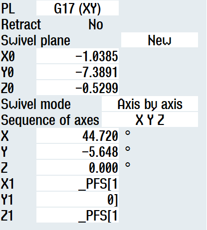
Hopefully this provides a clearer picture of the problem.
There are other many other ways to perform this task, I just wanted to see if I could get it this way.
-
24 minutes ago, crazy^millman said:
So when you run the machine with the output at 0,0,0 for those fields what does it do? I have programmed different FD machines using the standard CYCLE800 and never had a problem. What problems are you running to with the standard CYCLE800?
The cycle type is not the issue. I'm using CYCLE800 as an example. The problem is passing a 2D (or 3D) array to any cycle. Cycle800 works fine from the post and on the machine.
Currently I don't think this can be done. I believe only 1-dimensional array variables can be passed to cycles. I may rewrite what I'm doing to use that. However, if anyone has a solution for 2D/3D arrays being passed to cycles please post it.
-
6 minutes ago, crazy^millman said:
What kind of Kinematics are you working with? You show PFS, but my documentation on CYCLE800 shows this. What does your programming manual say the CYCLE800 is suppose to look like. When you click on the soft key on the control for the CYCLE800 what does it show you for each of them? Trying to reach out to SIEMENS Germany for help is a go back to DMG Mori and DMG Mori will tell you to contact SIEMENS. The post builder needs a good format that works on the machine then they can configure the post to support it.
CYCLE800(<_FR>, <_TC>, <_ST>, <_MODE>, <_X0>, <_Y0>, <_Z0>, <_A>, <_B>, <_C>, <_X1>, <_Y1>, <_Z1>, <_DIR>, <_FR_I>, <_DMODE>)
Kinematics are table/table A/C trunnion style, DMU85 FD. _PFS[x,y] is an array variable I've added to the machine using a UGUD (no need to pass it in every time and the data is saved.) You are correct with the Cycle layout. I'm trying to work with <_X1>, <_Y1>. However, when you try to pass, lets say _PFS[1,0], _PFS[1,1] this is what happens. It sees the comma in the field for the X1 value and escapes to the next field, in this case Y. Fills in the remainder of the array variable for X and then hits the delimiter. This error continues outside of the fields shown. In this example _PFS[1,0] should be entirely in the X1 field and _PFS[1,1] should be in the Y1 field. Z1 should be blank.
-
I'm having an issue with implementing an array on a DMG Mori (Siemens 840d) inside of a cycle.
The cycle that gets posted looks like this: CYCLE800 (0,"TC8",100000,57,-1.03847,-7.3891,-0.52993,44.72,-5.648,0.,0,0,0,-1)
What I'm looking for is something that looks like this: CYCLE800 (0,"TC8",100000,57,-1.03847,-7.3891,-0.52993,44.72,-5.648,0.,_PFS[1,0],_PFS[1,1],0,-1)However, the comma between the row and the column is escaping the field that it should be filling out.
Has anyone faced this issue before, and if so what did you come up with?
-
I'm sure you already got this one. But I've been using Emuge's Shur-Thread in Inconel 718 with really good success. TSC and have ideal LOC for ports.
https://www.emuge.com/products/thread-mills/shur-thread/spiral-unf/gfr351065044 -
I recently designed a macro program to do face grooves in parts that require a circular finish. I have not yet been able to test it and will keep updating the code here. However, if anybody else ever has a need for it. Here it is.
If you do try this code, do so with extreme caution. This program could be incredibly dangerous if operated incorrectly, (think broken part, spindle, tool, etc.) If you do use it, let me know how it goes here.
Cheers,
Caleb
; PROGRAM DESIGNED TO CUT CIRCULAR FINISH GROOVES THAT ARE NOT ABOUT A ROTATION AXIS ON A PART
; WORK OFFSET SHOULD BE SET TO CENTER AND TOP OF FEATURE DESIRED
; THIS PROGRAM IS VERY DANGEROUS, DO NOT STOP MACHINE DURING CYCLE
; SINGLE BLOCK, FEED HOLD, CYCLE HOLD, FEED OVERRIDE, AND SPINDLE OVERRIDE OVER CAN CAUSE CATASTROPHIC FAILURE
; PROGRAM DESIGNED IN INCH MODE, MAY BE UNSTABLE IN MM
; PROGRAM IS DESIGNED TO CUT FEATURE TO SIZE WITH NO STEPOVER
; ACTUAL SPINDLE POSITION CLOCK POSITION MAY NEED ADJUSTMENT, SEE LINE 60DEF REAL _F_DIA; FEATURE DIAMETER
DEF REAL _Z_DEPTH; DEPTH OF FEATURE
DEF REAL _Z_FEED; INFEED OF TOOL, AS LATHE
DEF REAL _T_TOOL_OFFSET; B DISTANCE OF TOOL IN SPINDLE, OFFSET OF TOOL FROM CENTER OF SPINDLE
DEF REAL _PI; PI CARRIED TO 5TH DECIMAL
DEF REAL _H_TRAVEL; ACTUAL DIAMETER TRAVEL, DIAMETER OF FEATURE - RADII OF TOOL*2
DEF REAL _F_RATE; FEEDRATE CALCULATION
DEF REAL _LOOP_CUT; CALCULATION FOR LOOP CUTTING
DEF REAL _FINAL_Z_CUT; FINAL CUT IN Z DEPTH
DEF INT _TOOL; TOOL NUMBER, OR NAME, BEING USED
DEF INT _T_HEIGHT; D VALUE BEING USED
DEF INT _RPM; RPM OF MILLING SPINDLE; THESE VARIABLES REQUIRE INPUT BEFORE RUNNING; INPUT OF 0 WILL RESULT IN ALARM
; ***INPUT DATA DESIRED HERE***
_F_DIA=3
_RPM=1
_Z_DEPTH=.050
_Z_FEED=.003
_TOOL=16
_T_HEIGHT=1STOPRE
T=_TOOL D=_T_HEIGHT; TOOL CALL, AND HEIGHT CALL
M6STOPRE
_LOOP_CUT=(TRUNC(_Z_DEPTH/_Z_FEED))
_T_TOOL_OFFSET=($P_TOOLL[2])
_PI=(3.14159)
STOPRE
_H_TRAVEL=(_F_DIA-(_T_TOOL_OFFSET*2))
STOPRE
_F_RATE=(_H_TRAVEL*_RPM*_PI)
_FINAL_Z_CUT=((_LOOP_CUT*_Z_FEED)-_Z_DEPTH)STOPRE
IF _F_RATE>500 GOTOF "MESSAGES_ALARMS_2"
IF _F_DIA<=.500 GOTOF "MESSAGES_ALARMS_1"
IF _RPM<=0 GOTOF "MESSAGES_ALARMS_1"
IF _RPM>=100 GOTOF "MESSAGES_ALARMS_2"
IF _Z_DEPTH<=0. GOTOF "MESSAGES_ALARMS_1"
IF _Z_FEED<=0. GOTOF "MESSAGES_ALARMS_1"
IF _Z_FEED>=.01 GOTOF "MESSAGES_ALARMS_2"
STOPRE
SUPA G00 G90 Z0.;
G17;
G54;
SPOS=AC(180.); ADJUST POSITION AS NECESSARY, INPUT IS DEGREES
G97;
X=(_H_TRAVEL*(1/2)) Y0.
Z1.;
Z.1;
G94 G01 Z.005 F25.;
G02 X=(_H_TRAVEL*(1/2)) Y0. Z0. I=-(_H_TRAVEL*(1/2)) J0. F=(_F_RATE) S=(_RPM) M3; SPINDLE ACTIVE, DO NOT FEED HOLD!!!
CUTTING_ACTION: X=(_H_TRAVEL*(1/2)) Y0. Z=IC(-(_Z_FEED)) I=-(_H_TRAVEL*(1/2)) J0.
REPEATB CUTTING_ACTION P=(_LOOP_CUT-1)
X=_H_TRAVEL*(1/2) Y0. Z=IC(_FINAL_Z_CUT) I=-_H_TRAVEL*(1/2) J0.; FINAL Z CUT
FINAL_DEPTH: X=(_H_TRAVEL*(1/2)) Y0. Z=-(_Z_DEPTH) I=-(_H_TRAVEL*(1/2)) J0.;CLEANUP PASS, REMOVES Z RAMP
REPEATB FINAL_DEPTH P=2; 2 SPRING PASSES AT DEPTH
X=(_H_TRAVEL*(1/2)) Y0. Z.005 I=-(_H_TRAVEL*(1/2)) J0.; BACK TO CLEARANCE HEIGHT
G01 Z.1 F25.;
SUPA G00 Z0. M05;
M30;MESSAGES_ALARMS_1:
STOPRE
LOOP
MSG ("PARAMETER MISSET, LOW")
M00
ENDLOOP
MESSAGES_ALARMS_2:
STOPRE
LOOP
MSG ("PARAMETER MISSET, HIGH")
M00
ENDLOOP -
I recently ran into an issue that I couldn't find a thread for. We have a fairly new post for Mazak 5x machines that suddenly decided to change how the feedrate worked in corners. Slowing the machine way down on all arcs. We discovered that despite "Adjust feedrate on arc moves." being unchecked it was still processing it like it was checked. We had to blink it on and off, then regenerate paths in order for it to take. This post is more for anybody with a similar problem in the future.
-
1
-
CTX Gamma 1250 CNC code parameter
in Industrial Forum
Posted
Hey Rusty,
Siemens 840d user here, although all the machines I currently work on are single channel. I did a little searching and found this video, which fully describes program structure, how the code should look, and a little bit about how the CAM system should output. TL:DR you need a couple of different programs. First is a .JOB which will contain a CYCLE208 and the master program names for each channel. Next will be the master program with the synch codes (which should look like this, WAITM(1,1,2)) and other relevant data. Last will be the .spf programs, which should contain all the cutting data.
This is fairly similar to my preferred output method of programs, even on single channel machines. However, CAM software wasn't quiet able to get me all the way there with posting out. I ended up making a python script to handle building of the master program, which works pretty well. Feel free to DM me if you want to see how that works.
A couple of notes, it looks like there is a pass option in the WAIT for individual channels. This should allow single channel operation, but without a machine to test it on I can't confirm. This YouTube channel has a lot of really good information on the 840d control, I would highly recommend watching to figure out some of the more powerful options on the Siemens control. Also, there is a machine simulator for the 840d called Sinutrain, this allows some basic simulation on your computer. Really helps when trying to diagnose problems like this with complex cycles, or macro programming.