Kalibre
-
Posts
49 -
Joined
-
Last visited
-
Days Won
1
Content Type
Profiles
Forums
Downloads
Store
eMastercam Wiki
Blogs
Gallery
Events
Everything posted by Kalibre
-
Mill-Turn tailstock and sub spindle in same program
Kalibre replied to kyle528's topic in Industrial Forum
You can define both your jaws and tailstock center in the stock set-up page. Tailstock advance/retract and part transfer still work. You're going to want to add M00 from your canned text before the transfer at the least for tailstock removal, it's even better to check the chuck clamping condition - i.e Nakamura lets you check it and alarm out (G471Y0102.7Q1.I9998. <- if not clamped GOTO9998, have alarm and message at N9998) or check some other machine state that will prevent crashing when the sub-spindle moves across. If you're going to do it a lot, it's worth making a spring loaded holder for the center and having it on the turret or in the tool chain (if that type of machine). -
What a lazy xxxx of a draftsman.
-
Haas UMC-750, tools vary .006 from beginning to end of day.
Kalibre replied to 5AXIS505's topic in Industrial Forum
Being low on coffee, and lazy I went with .00015"/1"/20F. New super small spindle cartridge? -
Haas UMC-750, tools vary .006 from beginning to end of day.
Kalibre replied to 5AXIS505's topic in Industrial Forum
Only time I've run into something like that was from the thermal comp being jacked. It's that or your shop is getting 850F warmer during the shift. -
OT - Subplates, Grid Plates for Kurt vises, what are you using?
Kalibre replied to volitan71's topic in Industrial Forum
It's not the cheapest, but it sure is good stuff. Used buckets of it saving parts for power gen, chemical plant, off-shore and mining customers. Machine table repair was a happy consequence, has saved a lot of heartache. -
OT - Subplates, Grid Plates for Kurt vises, what are you using?
Kalibre replied to volitan71's topic in Industrial Forum
A little belzona can give a guy a lot of first chances. -
OT - Subplates, Grid Plates for Kurt vises, what are you using?
Kalibre replied to volitan71's topic in Industrial Forum
We've had really good experience with Lang. You can put the studs on almost anything and haven't run into any problems with repeatability between set-up swaps. https://lang-technovation.com/en -
I was being generic with the run around bit, I'm sorry if it came across as directed at you. You've invested some time on this topic and dug up a lot of info for sure. Bit of a contradiction here, the whole manual PITA doesn't sound very perfect. All I have to go on here is wild speculation (not seeing anything workflow and am assuming gildemeister struktur for the .mpfs) , so grain of salt and all, but I used the mi$ as a dummy flag and the required syncs increment/output automatically (I'm sure there's other ways to accomplish it as well). If nothing is in gildemeister struktur, then none of what I've said applies.
-
This is the general run around I experienced, and at the end of the day it's just a lot of words to say they don't want to expend any effort to provide an actual solution. The 840D isn't a black box, the Siemens manuals are probably the most in depth I've dug through. Getting clean, fully functional code that gives the majority of bells and whistles isn't even a herculean task. It's syntax and formatting. Collision control is all $P_WORKAREA_CS_ variables, cycle shapes just need a few special characters to open in the graphics menu. Syncs aren't magic either, they just aren't the same as an M-code. INIT,START,WAITM,SETM and CLEARM - took an m$, buffer and a pretty short post block to sort out. DMG apps can't tell you what the CAM output should be, because they don't know outside of the control menu. The solution providers don't have enough customer demand to really want to bother, so say things like .... Sorry, I'll never understand why pretty lame excuses from both parties are accepted with CTX machines specifically, and I guess I have some residual bitterness at the memory of those interactions and no progress was made in the 6 years since apparently.
-
Contouring with 1/4 in ball end mill from bottom to top
Kalibre replied to zachdem1000's topic in Industrial Forum
I'll usually use a Thread Mill path. Keeps the tool engaged instead of repositioning like contour. Don't end up with the transition lines like a surface path and control comp for any required size adjustments. Can also back bevel undercut bores. -
Every time I have to do this I just finger cam it. Taking 0.197" of a 4" cylinder would be like: G90 G00 X3. Y0.2 Z.25 B0. Z-2. G01 X0 F150. G91 G01 Y0 B2400. F750. (feed depends on machine totally, B value is 0.2 divided by 0.03 step over) G90 G01 X-3. F150. It is easily doable in MCAM, I just hate needless bulk to the point I'd just do a G65 macro call from manual input if it happened often enough. Add a spindle orient with a turning tool and you can do turning ops this way too.
-
You can also just add .WPD to the folder name where the .MPF and .SPF are and cut/paste straight from the key without chancing something getting borked. MCAM -> posted MPF/SPF files -> Part CH1/CH2 .WPD folders on key -> into the control Only times I've done anything with .ARC is controller backups/parameter dumps and firmware upgrades.
-
The machine support from DMG is pretty top notch, they moved some mountains when my old shop was getting through the commissioning of our CTX. App support was decent, really good with anything controller related, absolute pants with CAM/post things. Overall, I really liked that machine. The only post solution IHS was willing/able to offer was an M/T environment that would post bare bones ISO. No Cycles (rough turning, threading, etc.), just good old line by line, "re-post if you need to change something at the machine". I ended up just adding a ton of modifications to MPLMASTER and made a CHOOK to generate the MPF and SPF files after being told by the post department that they couldn't do it. Hopefully there's better options available (doesn't sound like it from your post), but you guys should be all over them if the provided solution isn't coming close to expectation, it certainly wasn't provided cost free.
-
-
How to Change Cutter Comp. position in Lathe
Kalibre replied to @Mastercam's topic in Post Processor Development Forum
I've used canned text for drilling output and a few M codes/macro calls before, but I was ready to light my desk on fire if I missed a simple fix for psccomp behavior in this instance. Oddly, it only comes up in the lathe side of the post. Remove psccomp from ltlchg$ and comp doesn't output until it's cancelled. Yet psccomp isn't even part of mtlchg$ and it still reads it and outputs comp in plinout/prapidout just fine. Overall, it's an interesting quirk and was fun in a "throw your keyboard" kind of way to find a work around for. My post may be ugly as sin and would make anybody else cry, but the code comes out pretty and error free at least. I appreciate the insight Colin, thank you. I'll be sure to check out your channel, you're a wealth of good info on here. -
How to Change Cutter Comp. position in Lathe
Kalibre replied to @Mastercam's topic in Post Processor Development Forum
Thanks for the response Colin. I don't quite understand the Canned Text comment. Are you saying there's no reason for a solution like Werktuigbouwer's or the absolute clusterf*ck I've mashed together because there's already built in ability to control the output position? Or a person would still have to build the logic in to exploit that from NCI 1025 or similar? -
How to Change Cutter Comp. position in Lathe
Kalibre replied to @Mastercam's topic in Post Processor Development Forum
Anyone have any insight into why psccomp doesn't return an output when you just remove it from prapidout? It's in plinout, but doesn't seem to do anything as far as outputting comp. Milling ops and end of lathe ops force psccomp somehow as well. I found a dirty solution, just wondered what's actually driving in the background. -
Misc Value tirgger AFTER the Toolpath
Kalibre replied to Dave228's topic in Post Processor Development Forum
Have you tried putting it in your pl_/pm_retract? You might need to set a variable in the tool change and then call it there or ptoolend. Tough to tell with the vague description... -
There's a thread for this with some really good info on how to go about it with either a stack or buffer. You'll be able to pull the zmin for each tool and add whatever clearance.
-
Well, I finally gave up on the buffer route for this problem. I just couldn't get to the record I needed in the proper order with the way the post accesses the min/max values during processing. So, I ended up going the easier route and adding this into the pwrtt$ postblock. if t$ > 0 | gcode$ <> 1001, [ b4_min_depth = abs (z_min$) b4_min_depth = (round(b4_min_depth) + 0.5) "(", *b4_min_depth, no_spc$, 34, "MIN OVER HANG)", e$ " ", e$ ] Takes the min depth, rounds it and adds a 1/2" clearance. It adds it after the ptooltable output for each tool. Not exactly in the location I wanted it, but it'll do until I revisit it some day.
-
Seems like a pretty low bar.
-
Tool "Description" field parameter number?
Kalibre replied to nickbe10's topic in Post Processor Development Forum
The amount of things available to the set-up sheets that can't be read by the post is maddening sometimes. -
Was adding a little logic to an MPLFAN post and ran into a bit of silliness. Basically, I just wanted to set a variable based off of the value of plane$. Should be easy enough, it can only be 1 of four values and you can grab it from pretty much anywhere in a mill post. So off I went: if plane$ = zero, my_var = one if plane$ = one, my_var = three etc no matter what I did, it always spat out one. So, I just set my_var = plane$ and yup, big ol zero. Moved it all over the post to see if it would change the outcome and pulled my hair out realizing every nci line that it outputs plane$ for mill, it sure doesn't for lathe. I ended up tracing where the post digs out sg17-sg19 and was able to set my_var there, but seems like a bassackwards way of getting to it. Anyone know where/if plane$ is actually output anywhere during lathe toolpath processing and I missed it? Or does it actually not get treated the same as in a mill toolpath?
-
Tool "Description" field parameter number?
Kalibre replied to nickbe10's topic in Post Processor Development Forum
Even for 2020, the description and manufacturers name boxes are listed as N/A for posting. -
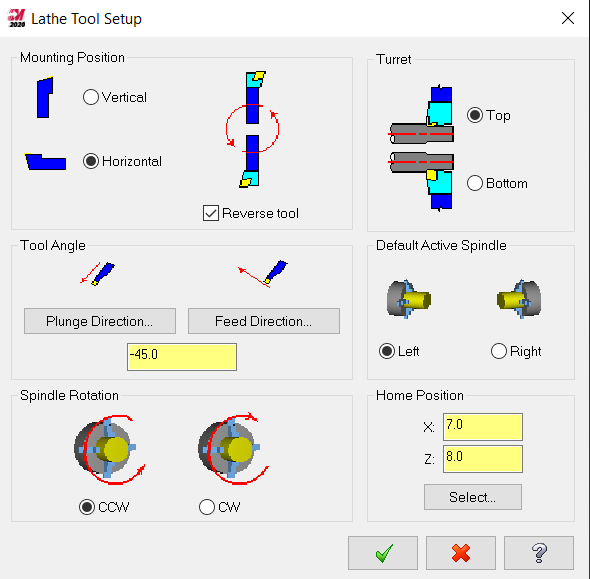
You can orient however you want on the tool set-up page. There's neutral OD holders in the standard tool library, change the insert to a VNMG if required and change the tool angle. Check the Define Tool parameters tab to make sure the compensation and tool clearances don't do anything funky (mostly on grooving tools).