


deezums
-
Posts
16 -
Joined
-
Last visited
deezums's Achievements
")
Newbie (1/14)
2
Reputation
-
What I am after is a single canned text entry that will output G30 P1 to move to a safe location, then M04 S5000 followed by a G04 P1. I would like for it to display as "throw chips" or in Mastercam, I've got editing the machine def down so that displays properly. It is pcan_06, so every time it is called the post will output M6 as that's the only logic check the post has by default. I would really like to mess with it further and see if I can pull variables from the linking parameters page so I can "clear chips" inbetween holes in a block using canned text, change at point. Or maybe I'll just make another custom drill cycle, that would probably be easiest. Colin, once again thanks for your help! I'm going to mess around with this and see if I can get what I'm after on my own! if cantext$ > five, [ strtextno = no2str(cantext$) strcantext = strcantext + strm + strtextno strm is a fixed variable, "M", and strcantext is fixed " ". strtextno is the buffer that is filled in the line before, in this case it's a 6. So, this makes M6s! I think that makes sense! Thanks again!
-
Hello again! I'm looking to modify canned text in my post, I run a lot of cavity tools and would like the ability to reverse the spindle and dwell for a sec before changing tools to sling chips off. I've found reversing to 6000 and waiting for a second is usually all it takes and would save the operator a lot of trouble. I've messed with gun drill cycles, so I have mastercam labeling the canned cycle properly, but now I'm having a hard time finding the bit in the post that actually outputs the text. I am trying to use scant6, I have the mpm_okuma post lightly modified but I found a few bits of the code that looked to do what I wanted, but it's still outputting M6's instead. #Cantext string definitions (spaces must be padded here) sm00 : "M00" sm01 : "M01" scant5 : "G04 P1" scant6 : "M04 S6000" strtextno : "" strcantext : "" From what I can gather, it's going wrong right around here. fmt "I" 3 iout #Arc center description in X fmt "J" 3 jout #Arc center description in Y fmt "K" 3 kout #Arc center description in Z fmt "K" 2 lead #Helical lead fmt "R" 2 arcrad$ #Arc Radius fmt "F" 15 feed #Feedrate fmt "P" 11 dwell$ #Dwell fmt "M" 5 cantext$ #Canned text # -------------------------------------------------------------------------- This would be perfect for a parts catcher or tailstock, but not for multiple codes from one canned text selection like I'm after. Since I don't want to break M00's, how do I go about switching this canned text off of this single number mode? Is this related to the coolant commands at all? I made a mpm_okuma.text file and put some stuff in there [canned text] 1. "Stop" 2. "OStop" 3. "Bld on" 4. "bLd off" 5. "M5" 6. "M04 S6000" 7. "M7" 8. "M8" 9. "M9" 10. "M10" 11. "M11" Not sure exactly where I found this in searching, but it's not working yet! Thanks in advance for any help!
-
What determines post processor block run order?
deezums replied to deezums's topic in Post Processor Development Forum
Thank you for the explanation, I've seen some crazy stuff done with post processors! I had one that would output conversational text files for accurite millpwr at a previous job, that couldn't have been easy! The pre-read loop, I think I've seen this one. If you step through the debugger just right it seems it's possible to get it stuck in this loop, it never actually posts code. I also see the 1006 parameter for my comments in the NCI file, I recall seeing this as "before" in the manual entry parameters. I can see now how having the comment# line in the header would post this "before" the next post block which should be the tool data gathering loop! Comments are buffered in scomm$, line by line? 1006 is posted as code so there are no scomm_str/scomm_end flags. This is the actual bit of code the NCI file will point at for every comment? It formats to uppercase and saves any spaces? Once again I really appreciate you taking the time to explain this! Knowing where in the post I'm going to jump next is going to be a big help! -
What determines post processor block run order?
deezums replied to deezums's topic in Post Processor Development Forum
That did the trick Colin, thank you! Volume 3 of the MP Post Ref guide has a predefined postblocks list on page 2-205, is this the order things are called in, just for my future reference? -
Hello I'm trying to modify a post processor, mainly just the order that certain blocks are run at the start of the NCI file. I am trying to post a tool list as well as a manual entry with both comments for setup notes and pallet change/stage codes. Currently my manual entry posts first, then the tool list. I would like this reversed as it makes no sense to have a tool list in the middle of code. Using the post debugger I can see how the NC file is generated, but I can't determine where or how to move the order of blocks as they run. Currently my post starts at pheader$ + pset_mach + pparamater$. This grabs the date and mastercam file name. Next, it jumps to pcomment$ + pcomment2 + pspc which I believe is from the manual entry window. After that is done it goes to ptooltable, so this ends up putting the manual entry above the tool list. I can't find any handoff from pheader to pcomment. I believe all I need to do is change the run order of pcomment and pwrtt, but I can't find where! Here is the block of code, with some commented stuff removed. Help please!
-
Where can I find the "additional paramaters" window?
deezums replied to deezums's topic in Industrial Forum
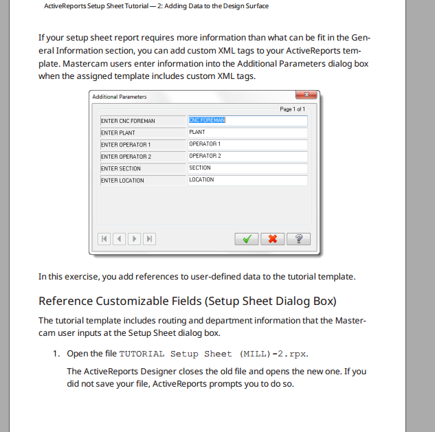
Browsing threads and saw this old one of mine, the solution was not deleting any of the original 8 parameters (machine, project, programmer, etc...) If you don't have all the above in your report, even hidden, it won't ever prompt for any additional parameters no matter how many fields you add! Now if only the additional parameters saved text... -
It seems this has been a problem for a while, at least according to this knowledge base article... https://kb.mastercam.com/KnowledgebaseArticle50303.aspx I need to output the maximum -Z value for each tool in a tool list, show me whatever linking parameter depth is greatest for any one tool no matter the WCS, should be easy . I program mainly horizontal mills, the relationship between the two WCS I commonly have (pallet 1 and pallet 2) are in no way related to the maximum drill depths or any tool planes. What will work is MIN-Z-TPLANE-O, but only if that tool number is only being used on one tool plane which is usually not the case, otherwise it will get confused and output N/A. I do not want to make setup sheets for every change in tool/comp plane, be easier to handwrite directions... I've been thinking about it and think I may have a solution, but I need some help translating it to C#. I would like to check OPERATION/DEPTH against whatever might currently be in the tool.rpx for MIN-Z text box which would be copied over from OPERATION/DEPTH on the previous operation with the same tool number if the value was null. If the depth is less than (more negative) than the current MIN-Z, replace it. If not, skip over it and do nothing. I do Arduino stuff every now and again but that's about it for my experience there. If someone can help explain how to pass data from the XML fields to the code (design name "txtMINZ"??) and then how to also hand XML data back to the tool list after the script is finished running I should be able to manage. If while running the setup sheet operation runs into two operations with the same tool, does it overwrite that line of text or modify only what's different? My plan depends on the latter being true, otherwise I can't see a way to get a previous MIN-Z value to compare against. Any and all help is greatly appreciated!!
- 1 reply
-
- 1
-

-
Where can I find the "additional paramaters" window?
deezums replied to deezums's topic in Industrial Forum
Thanks for the tip, I sent off an e-mail! -
Where can I find the "additional paramaters" window?
deezums replied to deezums's topic in Industrial Forum
I'm not sure I understand how it's meant to work still. I found a section in the active reports designer for adding custom XML tags to a template. The format is something like UXD-1 as a data field, and PARAMATER [FIELD]? [FIELD] in the text column of a text box. The brackets are just for clarification, I am not using them in the template as the help example shows. If I understand correctly, I should get a prompt for the additional parameters window since there are now extra XML tags in my setup sheet whenever I create a sheet using that template. It never pops up past the original setup sheet window and there aren't any arrows to tab around. "Multiple pages are indicated by the page count at the top right corner of the dialog box." says the help file, Which dialog box? The original setup sheet dialog box, or the parameters page that won't open? Is there meant to be a way to add them once in the report viewer window? Thanks for the help! -
Hello again, I'm trying to set up a setup sheet, heh, and I think I've about got it all figured out. I got a copy of the "creating setup sheets with active reports designer" tutorial from my reseller and it's helped out a lot. On page 64, they describe using additional parameters window to add extra XML tags so you can add more live data into a report. This is something I'd like to use but I can't find the window anywhere! The mastercam help file mentions it, configuring it from machine defs, but it still doesn't say where it actually is. Does it still exist in 2018? Thanks in advance!
-
Call positions after offset change?
deezums replied to deezums's topic in Post Processor Development Forum
Thank you everyone for the advice, I added the snippet of code to force XYZ moves after each operation and got some code which will run a lot better. N3 G116 T2 (13/32 DRILL) (MAX - Z2.) (MIN - Z-2.122) G15 H1 G00 G17 G90 X-.6875 Y-.03 S2182 M03 G56 H2 Z2. T3 M08 Z.1 G94 G71 Z.1 G83 Z-2.122 R.1 I.1218 J.1218 F13.96 M54 X.6875 G80 Z2. G15 H2 X.6875 Y.03 Z2. Z.1 G71 Z.1 G73 Z-1.622 R.1 Q.1218 F13.96 M54 X-.6875 G80 Z2. M09 M05 G30 P1 M01 I'm pretty familiar with the easy to change section of the posts, plus what you can change from the machine definition. Mpmaster is the default post "mpfan" correct? My Okuma post is based on the generic, so I assume this is mpmaster? Thanks again! -
Call positions after offset change?
deezums replied to deezums's topic in Post Processor Development Forum
Here is a drill cycle 30 thou from center of the part in Y, on offset 1 I get positions, then the code switches to offset 2 and tries to drill a hole in X without actually moving to the X value. The reason it doesn't think it needs to move is because the last hole it drilled was at the same absolute X value. Offset 1 is the top of the part, offset 2 is the bottom of the part. One part in, one part out per cycle is the goal. N3 G116 T2 (13/32 DRILL) (MAX - Z2.) (MIN - Z-2.122) G15 H1 G00 G17 G90 X-.6875 Y-.03 S2182 M03 G56 H2 Z2. T3 M08 Z.1 G94 G71 Z.1 G83 Z-2.122 R.1 I.1218 J.1218 F13.96 M54 X.6875 G80 Z2. G15 H2 Y.03 Z.1 G71 Z.1 G73 Z-1.622 R.1 Q.1218 F13.96 M54 X-.6875 G80 Z2. M09 M05 G30 P1 M01 I have no experience in modding posts outside of editing single bits on or off, where would I start with adding all that? If I call my VAR and more or less convey your post verbatim should it be an easy modification? Thank you both! -
Hello again! I'm trying to program some mill parts to run 1st/2nd op in the same program left vise/right vise, I'm doing this now with multiple offsets. I just noticed a problem though, if a coordinate has not changed between an offset change, mastercam will not reposition/recall the positions. The toolpath will run on the previous offset only because the absolute position hasn't changed as far as Mastercam knows, machine coordinates changed though. If only one value changes, only that axis will update in the code... Is there a way to make the post recall last absolute positions after an offset change without calling all positions for all holes, I don't want to make programs more bloated than they need to be. While I can pay attention and call code manually to do what I want I just know the first one I forget is going to bite me good... Thank you!!
-
I'm not sure how to analyze a solid, I'm 100% self trained mostly on mcam for sw, but if I go to the solids tab and right click the one solid and "check solid" I get zero errors. If I try and regen the solid, nothing happens. I can dirty and regen all toolpaths just fine, geometry is not gone as it can be with deleting driving sketches or whatever within MCam SW... In the solids tree I have one solid body (M15707-1) and under that I have a tree of all my operations, Facing, contour, G81 etc... I'm pretty familiar with the settings inside the verify window, as far as I can tell the stock model is correct, the part model is correct. I use the transparent stock and solid model to verify I'm doing right pretty often. I seem to recall a drill collision, so then I closed the verify window so I could increase drill length. Once back to the mastercam window nonstop parasolid errors... Sorry to be confusing, the engraving is solid modeled in my part. To make a toolpath on centerline I sketch (wireframe "create letters" sorry, I'm better with SW) text lines and roughly transform it over the solid model text. This is the only modification to the file done in the live window other than setting zeros and selecting geometry for toolpaths. Thank you both for the help!
-
It was an imported .sldprt file to start with, nothing more than text lines added in mastercam for engraving geometry.