LucasGC
-
Posts
146 -
Joined
-
Last visited
LucasGC's Achievements
")
Newbie (1/14)
8
Reputation
-
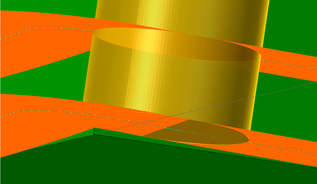
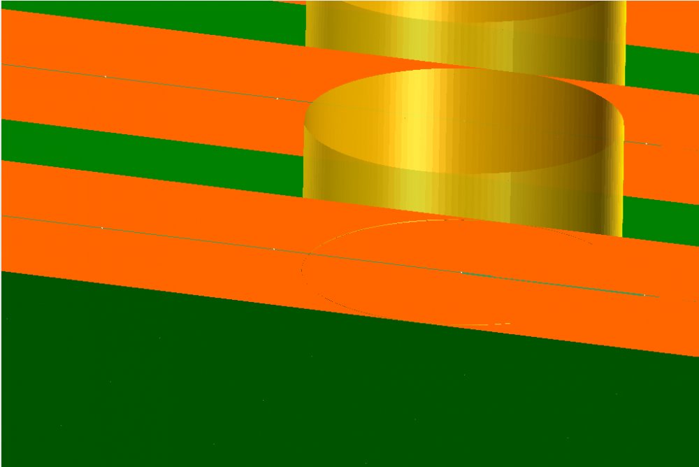
At the end of the line the tool is tilted and leaves a corner of the material on the part In the middle of the line the tool is oriented as it should be and makes a clean edge

-
Hi all, So I have pretty much a rectangle with a 2 degree draft angle Ideally I'd use 3d curve with tilt and select the bottom curve, but when I add depth cuts It doesn't take into account the angle it just offsets it upward. So when I try and make a swarf toolpath to use depth cuts, It looks like it will work but It's not as simple as a curve toolpath would be. When it's moving along the edges it does sort of a rocking transition where in the middle of the edge it will be straight up and down (at 2 degrees) but at the end it's already transitioning into the curve
-
Hi all, I'm wondering if there's a way to make a helix bore toolpath that does not move to the center of the circle for the retract. It doesn't make much sense to me if I am cutting a circle and then as soon as it finishes it goes full depth into my scrap I can use contour ramp but is there just a way to take it out of helix bore??
-
Hi all, Just a little confused on how transform works between planes. I have a part on a sheet in the upper left, and I have that same part on a different sheet in the lower right. If I translate the toolpath with the tool plane method and origin selected, the origin changes to the correct sheet, but the part stays in the upper left instead of moving to the lower right.
-
Hi all, Something strange happened to most of my files that i just noticed this morning. Most of the toolpaths that i created as a 'simple drill' toolpath were converted to drill/counterbore toolpaths. in the parameters when i go to 'cycle' drill/counterbore is selected with values in each of the boxes, and simple drill is not even an option in the cycle drop down any more. Has anyone had experience with this? Thanks, Lucas
-
So i split my model in half but i also had to split all of my toolpaths in two. Now i'm able to have an op that has stepovers at 0 and 180, or 180 and 360. While this sort of works I would really like to find a way to do it with only one toolpath.
-
maybe you could take a look and give me some tips? the start point doesn't give you many options to play with stepover at c0.mcam
-
Yep, it worked great. and yeah the roughing toolpaths don't have tilt. Next question kind of somewhat not really related: i'm using a morph toolpath to machine the sides of the cylinder, while keeping a 45 degree tilt away from the surface. that means each time my tool makes a full 360, so does my c-axis, and i don't have unlimited c. originally I wanted to use a zig-zag pattern and have my tool start at c0 and end at c360, then just reverse so i wouldn't have to have a c-unwind. i used the 'start point' option and while it starts where i need it to, the stepover is offset and it's at a very different point at the bottom of the cylinder. Is there a way to get the tool to start at c0?
-
three to five ax- conversion does it. thx.
-
hi all, Was wondering if there is a specific toolpath to use for roughing material with holder tilt. or a finishing toolpath that has a roughing option? i have basically a 3" dia cylinder that is 10" tall and i need to cut it out of a 5x5x10 block, i have a rotary toolpath for finishing but can't figure out how to get a tool down there to rough it
-
It's just one solid curve to one wireframe chain, i don't get the difference. if it were a few solid curves linked i would get it because the solid could have gaps on the corners. also i don't know if it's that it's not seeing the chain as on the drive surface, and if so would i have to create a wireframe curve as well as surface from solid? what would be the difference? I did fix it.. used approximate stepover instead of exact. Haven't messed with this feature much not exactly sure what it does. Thanks
-
variable radius will combine the endpoints for each line, so if you try and change the radius where the two fillets meet, it will just change them both. i tried adding points 2mm from each endpoint to make it blend but it just wasn't the same
-
Hello, I've got a morph toolpath that I used a .04" stepover value on for the first part. I'm now wanting to take it down to .02, and can't get mcam to process it. it gets about 60% through processing and then i get message ID 11521 - something went wrong during mapping - are input curves on mesh? I figure it could process at .04 what's different at .02 or .01? I'm using a solid, selecting faces for drive surfaces and solid edges for curves... Anyone have experience with this? Thanks
-
This did work, definitely an abstract shape. I ended up doing something different, but this is a valuable process for the future, thank you. What i ended up doing was I just made the first radius, and then made the second one match the first, and the third match the second and so on. i went up to 6 decimal places on some. this means the fillets aren't equal on most of the edges... but at least they're smooth.
-
I guess i was expecting a wedge shape that blends the two. if the fillets stopped at a 90 degree i would think i'd have a nice triangle left. I will try and get it to do what i'm picturing by sweep cut