andyjobo2
-
Posts
15 -
Joined
-
Last visited
andyjobo2's Achievements
")


-
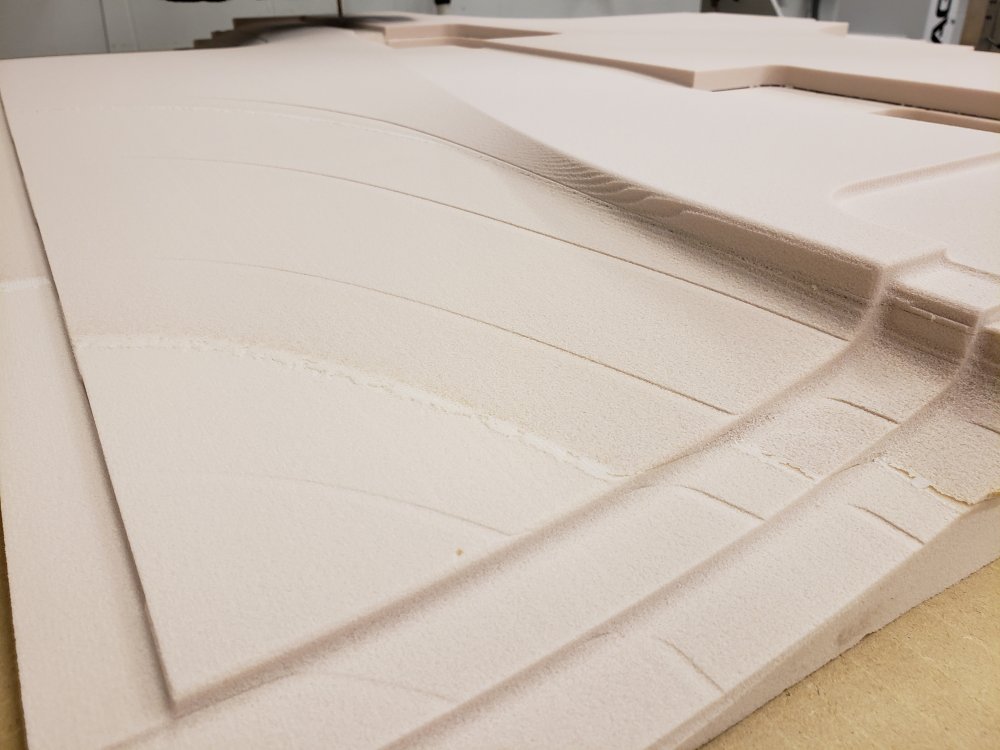
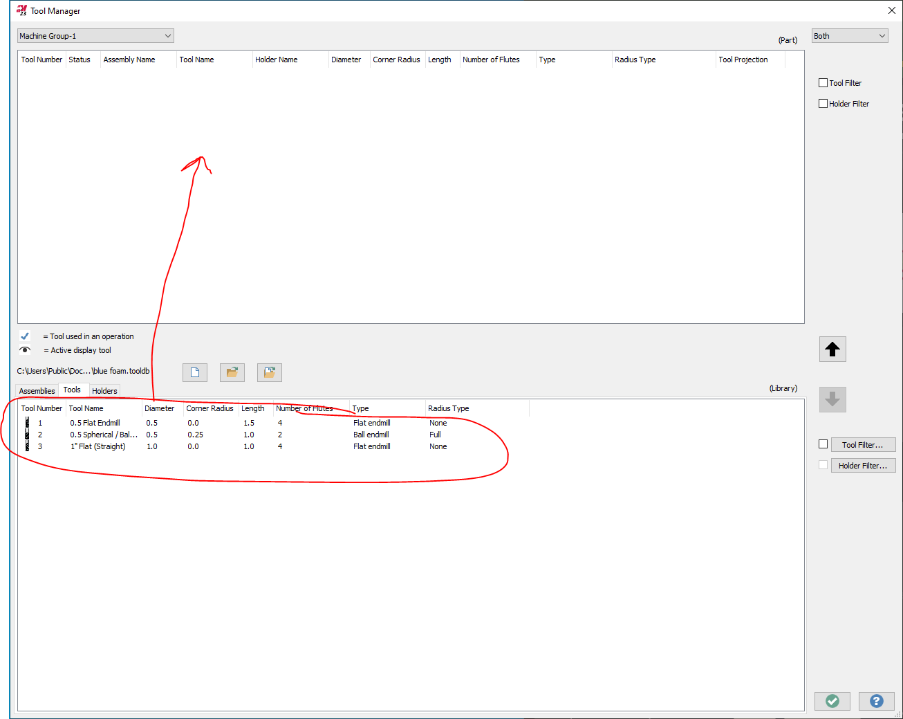
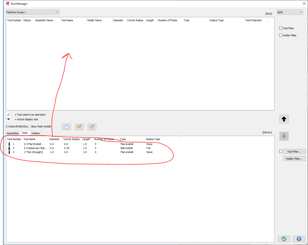
I am wondering if there's a way to have tools from a Tool Library automatically load into the Machine Group? Please see the attached images, which depict the Tool Manager (found under the Machine Group Properties/Files/Libraries/Tool Manager). The first image shows what I currently have. The Tool Library is automatically loaded into the bottom half of the window. The second image show what I would like to automatically happen (if possible); the tools need to be listed under the Machine Group in the upper half of the screen. Currently, I have the Tool Library and Operation Defaults set to automatically load when I select my machine, but I still have to manually drag the tools up to the machine group each time. If I don't drag the tools from the Library into the Machine Group, then the Operation Defaults don't automatically use them.

-
Processor: Intel Xeon CPU 3.7GHz RAM: 16 GB GPU: NVIDIA Quadro P600 Everything is up to date, as the system is only a month old. It bears mentioning that i work at a university and this issue is present whether I use MasterCAM from my office or my shop (different systems/specs). We just updated from MasterCAM 2021 to 2022 a couple of weeks ago and that's when I started noticing the "lack of selection colors" (among a plethora of other more bearable issues).
-
Indeed, Use Glow Highlighting is selected, and now that you mention it, I'm NOT noticing a glow either.
-
We just updated to MasterCAM 2022, and now whenever I select a solid or a face it is difficult, sometimes impossible, to distinguish that I have actually selected anything. Two specific examples which I do very often. First, selection of a solid when setting up a Bounding Box. When asked to select which solid to bound, when I click on a solid there is no change in color to tell me that it was been selected. Second, selecting "Model Geometry" for a 3D operation such as Raster. When I'm selecting which faces for the operation to use, clicking on a face changes it from dark grey to "slightly less dark grey". It is *very* difficult to distinguish between what has been selected and what hasn't. I have looked under File-Configuration-Colors, but can't seem to find the choice that will change the colors for the issues I'm referring to above. Please advise.
-
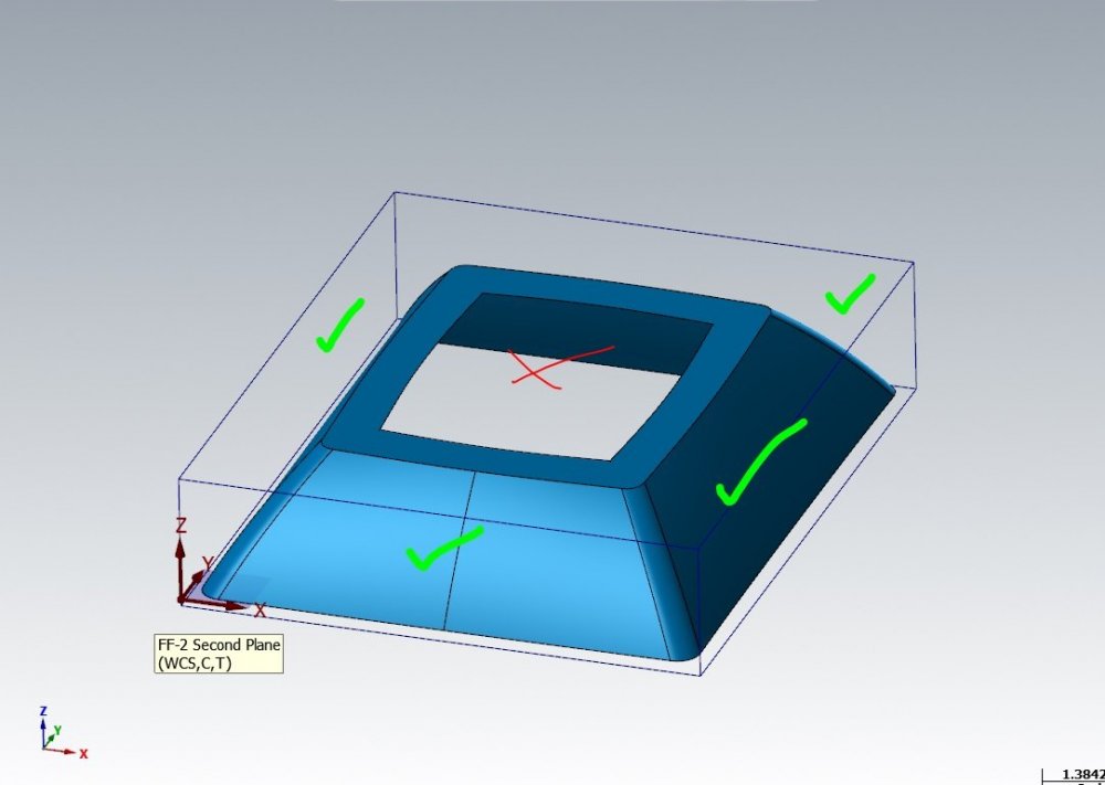
I am trying to use the 3D operation Area Rough to clear away material before I can perform a Waterline on the part. I only want the area rough to clear material away from the upper/outside of the part, but no matter what I do it still generates toolpaths on the inside hole section . I don't need the machine to go there, because this material was already cleared away while cutting the opposite side of the part during a prior setup. Please advise. Is there a parameter option that can tell the machine to stay away from the inside region?
-
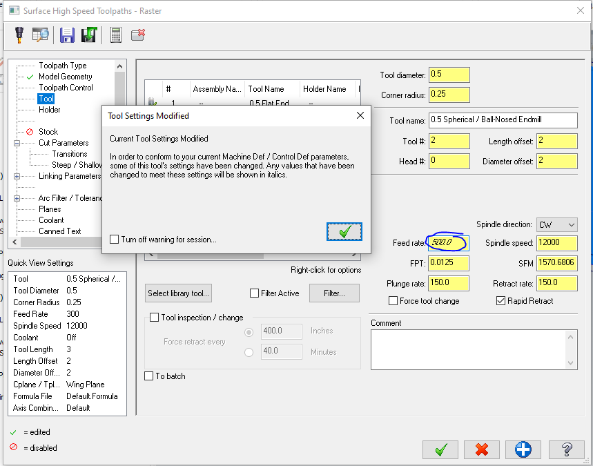
I am attempting to set my feedrate to 800 ipm, but MasterCAM is displaying a warning and then capping it at 500. Is there a way to override this setting? (Aside from manually changing the code after post-processing. I'd like to make this change within' MasterCAM itself.
-
I'm so dumb, I realized I don't need to upload the file. I can just upload it to Google Drive and share the link. https://drive.google.com/file/d/1MDPpLLsjuJRh1h3vRi5LlR03L3S65VDY/view?usp=sharing As a warning, the file is oddly large and may cause MasterCAM to act sluggish. I didn't create the file, so I don't know why it's like that. I'm just in charge of CAM'ing it. Also, here's a screen shot of the ETG where the G won't generate.

-
Hi 5th Axis CGI, thanks for your reply! I am unfamiliar with the setting you've referenced. Could you please go into more detail about where it can be found?
-
Hi all, I'm using the Dynamic Mill operation to cut letters into the surface of a piece of acrylic. Some of the letters are not having toolpaths generated. I've attempted to re-chain those letters, tried putting them into a separate operation, but nothing seems to work. It's not always the same letter either. For example, I need to cut the word "electronics", but only one of the "c"s doesn't generate. In another instance I need to cut the letters "ETG" and the "G" won't generate. Unfortunately, the file is too large for me to upload here (even as a ZIP folder, jeez), so I'll gladly email it to you if you contact me at [email protected]. Any help would be greatly appreciated. Thanks.
-
Operations transition THROUGH my part
andyjobo2 replied to andyjobo2's topic in Machining, Tools, Cutting & Probing
OOF, I feel silly because I was sure I had them all set correctly. I guess sometimes it just takes another pair of eyes to point out the obvious, haha. Thank you very much for your help. -
Operations transition THROUGH my part
andyjobo2 replied to andyjobo2's topic in Machining, Tools, Cutting & Probing
Sorry I didn't upload the file before. It is attached here now. Fan shroud inner mold 1.emcam -
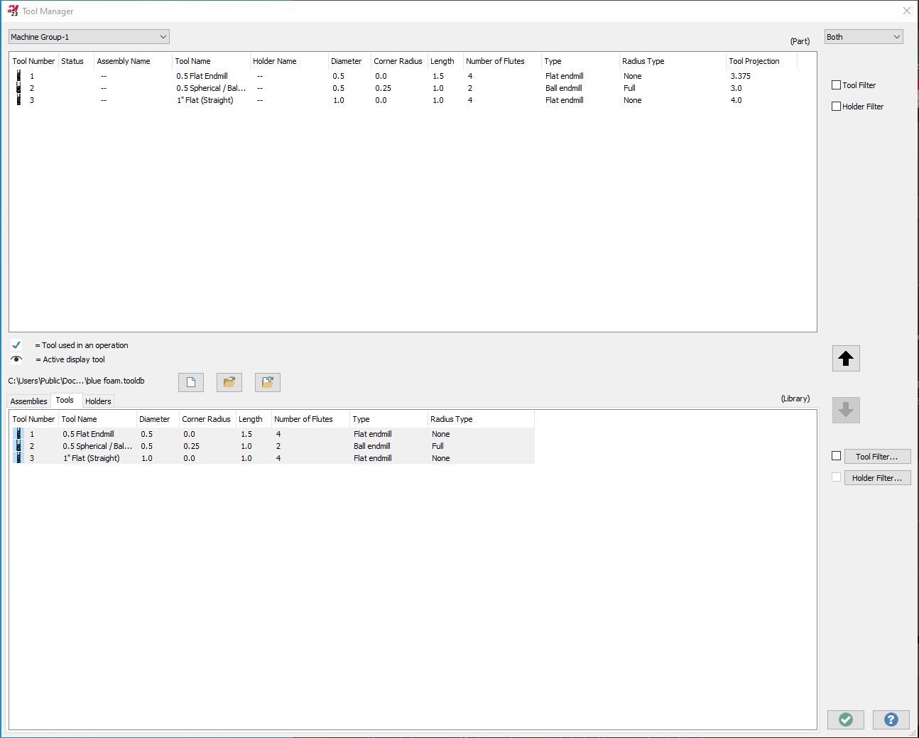
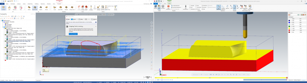
PLEASE, why does this happen and what can I do to avoid it in the future? If you look at the screenshot. I have circled in red a path the tools takes from one operation to the next which goes RIGHT THROUGH MY PART. But in the simulation ("verify") it did not display this egregious behavior! I missed it and botched my part. INFO: I have clearance planes set above the part for *every single operation*. I would expect the tool to go to this clearance plane before making any moves between operations.
-
Hi all, I work for a University and we just updated our MasterCAM from 2019 to 2020 and I have been experiencing a *lot* of small bugs which are eroding the quality of life. The one in particular that's really annoying me is that I cannot get a plane to remain displayed in the graphics window. In 2019 I would go to the Planes tab and click the gear icon at the top and select "Always Display Gnomon". In 2020 I see that this has been replaced with "Display" column in the planes manager. When I click this column to put an "X" in it, the plane does display. But it goes away the instant I begin working in the graphics window. Mind you, "DISPLAY" still has an X in it. Can anybody else verify this bug and/or offer solutions to always display the working plane in the graphics window?
-
Area Roughing cutting in too far?
andyjobo2 replied to andyjobo2's topic in Machining, Tools, Cutting & Probing
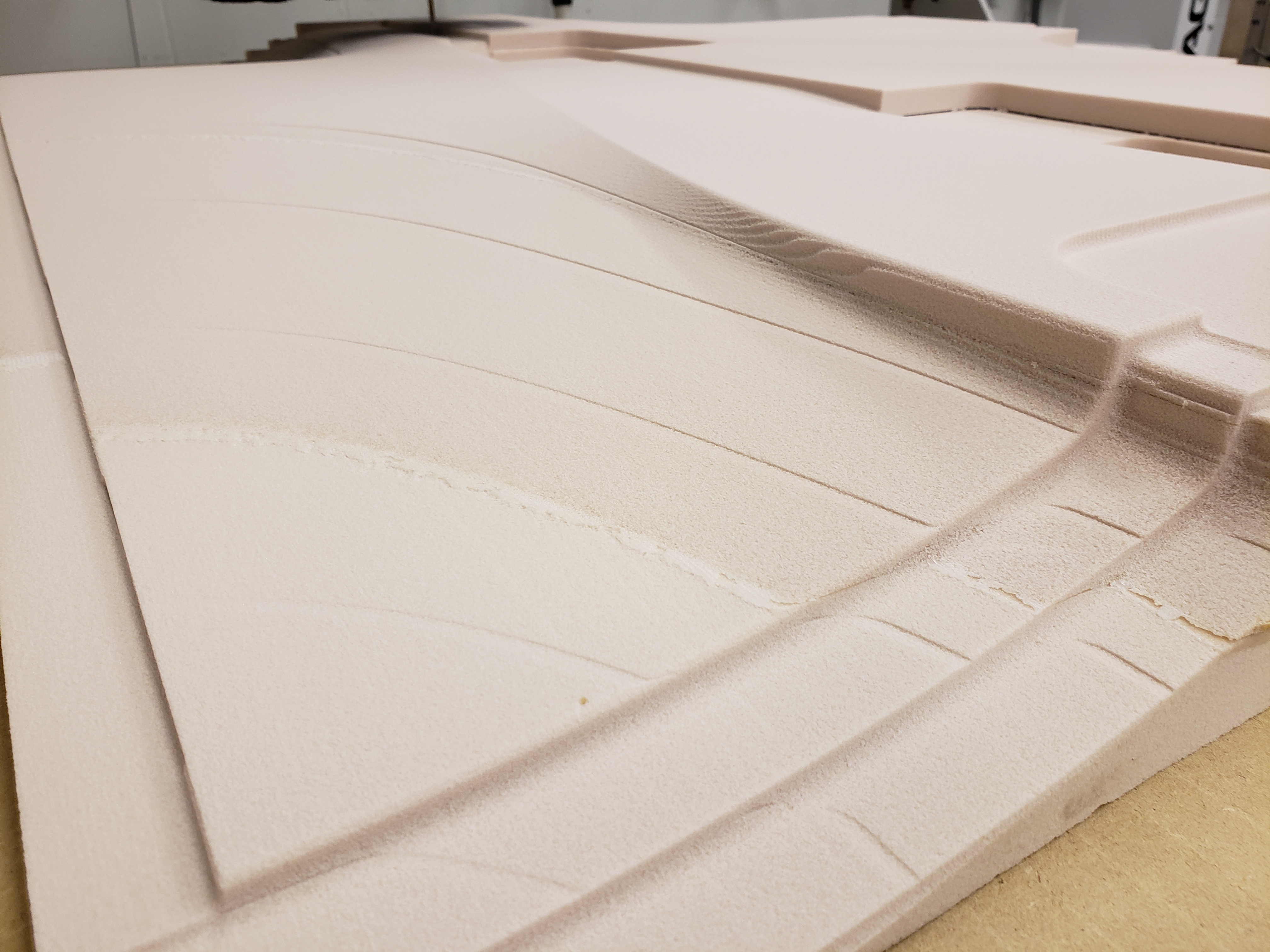
Here is the file. (Sorry I couldn't edit the original post, the MasterCAM website keeps giving me an error 404 whenever I click EDIT POST) (7) _V2 Mold Undertray Side Floors Layer 2.zip EDIT: Upon further inspection, I believe this is a problem with my machine. The z-axis seems to be getting *higher* as the machine cuts its raster across the part. Once I figure out how to delete my post, I'll do so. Until then, this message will have to serve. -
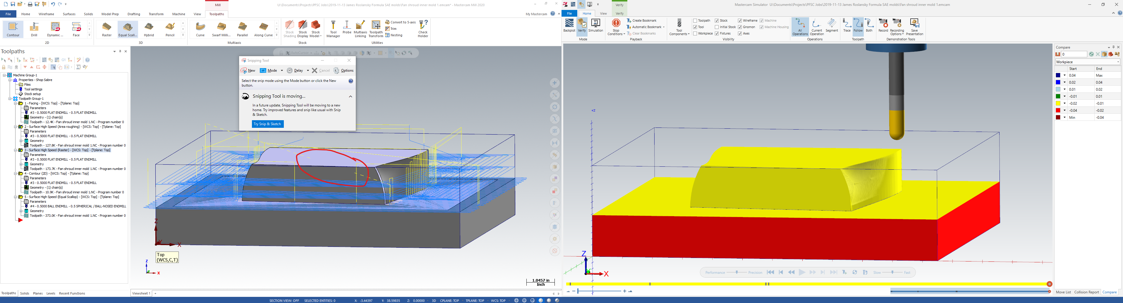
The Area Roughing operation seems to be cutting into the part. When the Raster operation runs across, you can see striations where the roughing operation has cut too far into the piece. Looking for advice to help correct this. (Picture attached for reference of what I'm talking about)