


Jespertech
-
Posts
119 -
Joined
-
Last visited
-
Days Won
1
Content Type
Profiles
Forums
Downloads
Store
eMastercam Wiki
Blogs
Gallery
Events
Posts posted by Jespertech
-
-
honestly, I'd go for dynamic before peel mill in this situation.
any chance you can post a file?
-
 2
2
-
-
10 minutes ago, crazy^millman said:
On that kind of machine it will have to be surface machined. There is no way to cut it with a regular contour toolpath.
that's what I'm struggling with now, I've been spoiled with multi-axis toolpaths so I never run into this problem. Would it be possible with some long winded geometry modification through C-axis contour or would it have to be done with a multi-axis toolpath?
-
 1
1
-
-
Shoot! well there's always C-axis contour.
-
You can try using a Swarf toolpath to finish this feature.
-
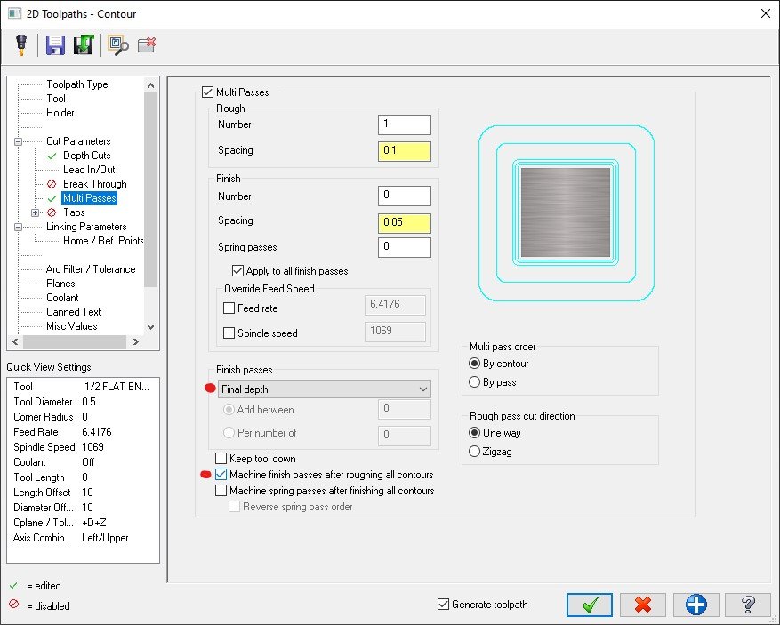
after trying to recreate the situation I now see what you're talking about, It wants to finish the depth cut before adding the finish passes in multi pass. when really it would be nice to incorporate the two as you said.
-
1
-
-
In the multi passes box do you have finish passes set to "final depth" and the "machine finish passes after roughing all contours" box selected?
-
This is kind of on topic but not really, but it's an approach that works well for me that others might find helpful, or perhaps I'll find a better way through sharing this.
Usually I'll create sub groups within my spot drill cycle and label them for each set of holes.
for example I have 4, 3/8-16 tapped holes on the face of my part and 6, 1/4-20 tapped holes at the bottom of a C-bore.
That way when I go to create the drilling cycles all I have to do is copy and paste the specific toolpath then change the tool and parameters and I'm done.
I'll then do the same for the tapping cycle.
This has improved my workflow and programming time quite a bit in parts that have a lot of different hole features.
-
23 hours ago, nickbe10 said:
Have you tried the CMM forums?
Yup, I got some good input.
The issue I have with some of the other forums is it seems to be a lot of commission based responders.
I'm looking for more of an honest review from a hands on perspective. Which, in my experience, this site is the best for.
-
My company is looking into getting the Polyworks inspector software for our CMM, we're currently using mcosmos which I get is not the most user friendly interface at first but it is definitely a powerful package. My question is has anyone here used Polyworks and can offer some pros and cons that they have found?
-
1 hour ago, Colin Gilchrist said:
By the way, check out the link in my signature. I've got an entire Basic Post Processing Class which was recorded back in 2016, which I've uploaded to YouTube. Be sure to watch the "Office Hours" video sessions, where we are doing the bulk of the "hands on" post development work.
I've been meaning to watch through your series for a while, now that I'm getting some hands on experience it's definitely time to do so.
-
1
-
-
Next rounds on me!

-
1
-
-
20 hours ago, Colin Gilchrist said:
That should be where you want to add it. Basically >
psof$ = "the 1st tool change operation" in the Post
ptlchg$ = "the next 'actual' tool change operation
ptlchg0$ = "null tool change, tool number repeats"
Thanks Colin , everything at this point is helpful. I've managed to make some decent modifications to my post to eliminate having to edit so much after the fact. Most of which is aesthetics, but even after struggling through what I figured out yesterday today seemed to be a little easier.
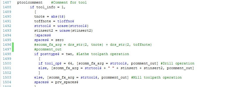
I'm currently trying to remove a single line "tool comment" note from my "GENERIC HAAS ST 4X MT_LATHE"
I've added the spaces between tool changes, the "N" numbers at the start of each tool path and the G53 safe retract at the start of each cycle, all of which I've been doing by hand through CIMCO. so that's a huge improvement and a big time saver.
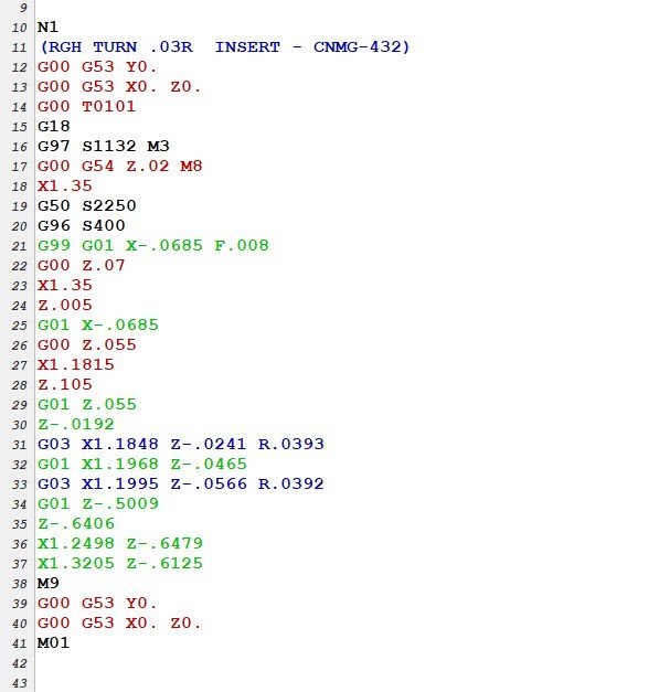
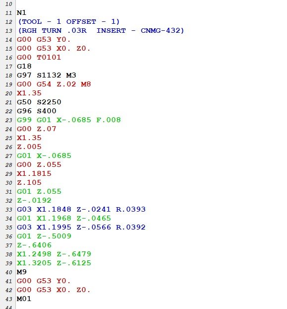
my next conquest is to get rid of the "(TOOL - 1 OFFSET - 1)" in between my sequence number and tool info comment.
-
Hot damn! I think I got it
ptlchg$          #Tool change
      pcuttype
      toolchng = one
      if prog_stop = 1, pbld, n$, *sm01, e$
      if prog_stop = 2, pbld, n$, *sm00, e$
      pcom_moveb
      pcheckaxis

**added line here**  " ", e$

  c_mmlt$ #Multiple tool subprogram call
      ptoolcomment
that seemed to do the trick, hopefully nothing else got weird.
-
1
-
-
@JParis - I'm struggling to figure this one out, I'm not sure where in the post to add the quotation marks to get the space.
I'm very new to post editing and the more I play around the more I'm learning which is great.. but also extremely time consuming
 .
.I've tried adding it to a few locations with no luck, would it be before the tool comment in the "psof$" block of code?
psof$            #Start of file for non-zero tool number
      pcuttype
      toolchng = one
      if ntools$ = one,
        [
        #skip single tool outputs, stagetool must be on
        stagetool = m_one
        !next_tool$
        ]
      pbld, n$, *smetric, e$
      pbld, n$, *sgcode, *sgplane, scc0, sg80, *sgabsinc, e$
      sav_absinc = absinc$
      pcom_moveb
      pcheckaxis
      c_mmlt$ #Multiple tool subprogram call

                         **HERE**
ptoolcomment
      comment$
      pcan
      pbld, *n$, *t$, sm06, e$
      pindex
      if mi1$ > one, absinc$ = zero
      if use_rot_lock & (cuttype <> zero | (index = zero & prv_cabs <> fmtrnd(cabs))), prot_unlock
      pcan1, pbld, n$, *sgcode, *sgabsinc, pwcs, pfxout, pfyout, [if use_3d_approach, pfzout],
        pfcout, [if nextdc$ <> 7, *speed, *spindle], pgear, strcantext, e$
      if use_rot_lock & cuttype = zero, prot_lock
      pbld, n$, [if not(use_3d_approach), pfzout], scoolant, pstagetool, e$
      absinc$ = sav_absinc
      pcom_movea
      toolchng = zero
      c_msng$ #Single tool subprogram call
-
Just now, JParis said:
There is likely a 2nd Toolchange section...scroll down and you should find it
yep, I was actually just editing my original post to say that I found it lol thank you
I'm embarrassed with how long I've been manually adding N codes to my tool changes for my lathe post, hoping this fix will work and save me time in that regard as well.
-
I'm actually trying to accomplish the same thing but for a prototrak post.
I modified the code as Craig-B suggested but now I only get the N number for the first tool in the pgm.
The following tool changes don't produce an N number.
Any idea what could have caused this?
-
Have you tried duplicating your top plane and then rotating it -90 degs then setting that as your WCS, C +T plane. It should flip the X's and Y's for you.
-
4 minutes ago, cncappsjames said:
Inverse Time Feed (G93) is one of the ways to get your machine to cut with one or more rotary axis in the cut. The simple explanation that F isn't a function of Feed rate, it is a function of time. The program is telling the control to take X number of units to make this move from one point to another. The program controls it. As JP aluded to there are two ways to express the function; Degrees Per Minutes or Units (mm/in) per minute.
Another common method is Tool Center Point Control (G43.4, G43.5, etc...). In TCP the control is making the calculations so you'll see feed rates as often as you wouls in a contour type path; plunge moves, feed moves, and retract moves. And the F is a function of feed in Units Per Minute.
HTH
thank you, I feel like I just stumbled into a whole new level of heightened understanding within the multi axis world. It all makes so much sense now, especially in situations where I'll need simultaneous 5 axis cutting motion. It seems so silly to think that there could be one feedrate in IPM for 5 independent axis' , but as of an hour ago that's exactly where my head was at.. You guys rock, thanks again.
-
1
-
-
37 minutes ago, JParis said:
OK, with that posting, I am guessing this is a 5 axis cut.....or at the very least a 4 axis simulataneous...
How does your machine want that feedrate? Is it using DPM(degeree per minute) or inverse feedrate?
That feedrate might make perfect sense to the machine
ahh so there is more going on here than I was initially aware of, the code is generating a G93 for inverse time mode. Doing a little research it makes more sense to me. I was thrown off because I'm used to most of our rotary work being posted using DPM. I'll have to wait until I get the part set in the machine to try it out and make sure that it likes what I'm feeding it.
thank you for the input, and opening my eyes a bit more into the different cutting modes.
1 minute ago, crazy^millman said:That is correct that is Inverse time and per the Mastercam Control Definition(MCD) it is doing what it is told to do for output. Problem is the Mastercam Machine Definition(MMD) has been told that the max inverse feed rate is limited to 999.9999 when the machine might be able to handle 9999999.999. If you go into the MCD and change the feed like any other MP based post that has been hooked up correctly then you would get a changed output, but the problem is the age of this post it is not using the MCD for NC output. You need to go into the post and change that output here and the max feedrate that should be controlled by the MMD.
#Feed control settings
convert_rpd$ : 0 #Convert rapid to rapid feed
use_fr : 3 #Output feedrate
#0 - programmed feedrate
#1 - inverse feedrate
#2 - inverse feedrate on 5 axis continuous
#3 - inverse feedrate on motion with rotary
inv_fd_typ : 0 #Calculate feed location options
#0 - inverse feed at tip
#1 - min-max on flute length
#2 - tip to pivot on tool length
#3 - min-max on flute length to pivot on tool length
inv_sec : 0 #Inverse feedrate is in seconds
radius_fr : 0 #Use axis radius distance (pri_feed, sec_feed), user must add code
rot_feed : 0 #Rapid rotary motion only feed options
#0 - convert to G0 rapid
#1 - apply rapid feedrate
maxfeedpm : 500 #Limit for feed in inch/min
maxfeedpm_m : 10000 #Limit for feed in mm/min
maxfrinv : 999.99#Limit for feed inverse time
fix_fr : 1 #If feedrate is zero, apply these values
deffeedpm : 1. #Default for zero feed in inch/min
deffeedpm_m : 25. #Default for zero feed in mm/min
deffrinv : 500. #Default for zero feed inverse time
inspect_delay : 0 #Delay inspection point until null toolchange for safetyChange the use_fr from 3 to 1 if you want to try the operation feed rate on the machine.
If you want to try a higher number in inverse time then change the maxfrinv from 999.99 to 99999.99 and try it on the machine.
You answered my next question before I even had to ask, Thank you!
-
Good morning fellow bull fighters,
I'm working on a fairly simple part, which honestly makes my situation all the more frustrating. I've accomplished exactly what I was trying for as far as backplot is concerned.
yet when I go to post the code it generates an absurd feedrate (999.99).. I've tried tweaking my settings in machine definition / control definition but nothing seems to be working.
Has anyone else experienced this problem and if so how were you able to resolve it?
I wanted to reach out here first before emailing my reseller in case it's something simple that I'm just overlooking.
-
unfortunately I can't open the file you shared it's either a mcam 2023 or a home learning edition file. I'm still currently sticking to 2022 at work.
-
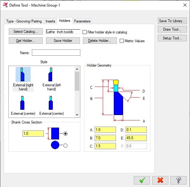
right click tool in library, edit tool , then adjust the dimensions highlighted in yellow.
-
Do you have access to the multi axis toolpaths?
-
If you have the old model saved on a different level in the same file make sure that level is turned off before running verify otherwise it will import it as a workpiece.
Tips to establishing a world class programming department?
in Industrial Forum
Posted
After years of grinding it out on the floor the powers that be have blessed me with the opportunity to wrangle in our programming cowboys, slap a "department" tag on them and refine this into a high functioning "world class" programming department.... Yippy.
My hope with this post is to get examples of well-rounded programming departments that you all have been a part of.
What made them successful? what made them fail?
Is there specific training offered that can help improve the utilization of machine definitions, tool/holder libraries and setup sheets that will keep these boys in their (Mcam) seats. and not have to run in every job that gets posted to the floor.
I have already reached out to my local reseller and will be discussing options with them on Monday but seeing as how I owe most of my programming success to this forum. I wanted to get real advice from you guys as well.
Thanks for the time.