


Jespertech
-
Posts
119 -
Joined
-
Last visited
-
Days Won
1
Content Type
Profiles
Forums
Downloads
Store
eMastercam Wiki
Blogs
Gallery
Events
Everything posted by Jespertech
-
Thanks guys, the part itself is just a flexible mounting bracket so dimensionally we've got a mile. It was more of a lesson for myself in the modeling capabilities of MC. I'm a sucker for making solids even when it isn't necessary and this was a good challenge for the day. I ended up extruding the 2d profile and then created wireframe on offset planes to cut out the rest of the shape. There are some spots around the rads' that may not be perfect but I think overall it'll work. It would be nice if eventually they can integrate a system where you can translate/project solids around solids to shape different profiles.. I may be getting dangerously close to SW works territory now though . CURVE SOLID.mcam
-
I'm struggling here trying to figure out the simplest way to take my planar solid and project it along set curves. I can take a very long winded approach at accomplishing this but feel like there has to be a simpler way. if anyone can help it would be much appreciated. MC22 file included . CURVE SOLID.mcam
-
I know, I've been going crazy trying to figure it out. I recently updated to MC22 and thought that maybe this was just a bug. I wanted to see if anyone else was experiencing the same problem. This is the first time this is happening for me where it wont save it. But I'll keep digging and hopefully will get it sorted out soon. Thanks for the response Ron, have a great weekend .
-

Planes when Milling in a Lathe/Mill Turn
Jespertech replied to Corey Hampshire's topic in Industrial Forum
Have you tried orientating your part and setting your WCS on the D+Z+ plane. Then depending on the Mill ops you can either select the Right Cplane (axial) or the Back Cplane (Radial) .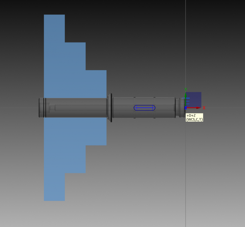
-
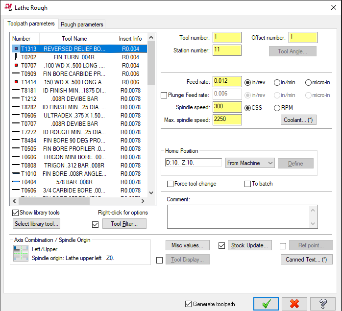
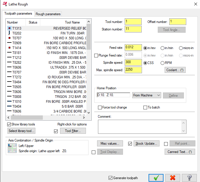
Does anyone know if it is possible to customize and save the toolpath parameters tab menu? seeing as how I cant change the window size I would at the very least like to be able to adjust the order of the tabs up top. I'd like to be able to hard edit this so that it displays Tool#, Tool name , Tool radius and remove the "status" tab. I'll include images to further explain what I'm talking about. Thanks in advance.
-
You should check Grab cad too, I found a decent ironman helmet a couple months back.
-
I've been putting some hours into one of the more complicated parts I've done to date. It's mostly 3+2 but there are a few features that require a live 5 axis approach to achieve. The file I provided has been almost completely stripped but I left in one of the pockets and the toolpath that I came up with to try and machine this nuisance. Any and all feedback would be greatly appreciated. If there's a better/ cleaner approach or a "go to" toolpath that anyone uses when tackling parts like this I'd be very interested in learning the ways. Thanks in advance. MULTI AXIS POCKT.mcam
-
Have you tried holding shift while selecting one side of the arc to force the chain? I believe you could also select both arcs and then join entities to create one circle.
-
Thanks Ron, that definitely helped . I need to do more research into the different miscellaneous integers and how they effect the post. Most importantly for me setting the offsets to zero for the G54 is going to save so much time and help steer me towards a more "post and go" friendly environment. As for the deburr tool path she's a thing of beauty, I need to break my habit of leaving the edges sharp and trying to drive the path as if its a 2d chamfer. Thanks again for taking the time to help, Its much appreciated.
-
hey guys, I'm working on a pretty basic part. nothing crazy. A couple holes, a few pockets bing bang boom, piece of cake.. so I thought. Everything when ran through backplot looks correct yet when I run It through verify the radi on my pockets seem to be incomplete.. What made this known to me at first was the digging in of the tool on my debur toolpath. I was going to post and go and see if it was just a verify malfunction but then the code for my debur toolpath really set me off course. I've tried adjusting my plane selection for the tool to correct the errors but nothing seems to work. I do have a multi axis seat and have used these toolpaths for mill turn parts before with no issue. I figured I'd come here to see if there is a workaround for this or something simple that I'm missing. bonus points if you can assist me on figuring out how to keep my g54 as the only plane while using toolpath transform in the post. I've been manually deleting the various work offsets on those toolpaths to get by. emastercam deburr.mcam
-
Don't you just love when they do that
-
hey guys, My company is quoting out a new machine and our rep is pushing for us to switch over to the quick grip collet system. If anyone here has any working experience with these and can offer some pros and cons, id love to hear them before we make our final decision. One thing that might be an issue is the housing seems bigger than the standard royal accu length collet chuck which could cause some clearance issues with our radial tools.
-
Thanks Colin, I've been meaning to check out some of your youtube videos on this matter. This forum has definitely given me the confidence to venture deeper into the world of post editing.
-
Okay, I'll do some digging and see if I can figure it out. Fortunately my resellers are rockstars and can definitely make this happen. I just figured it would be a good introduction to self editing. I like the switch idea a lot, a few of the machines I program for need the X first then Z retract for clearance issues. I spend a little too much time editing after post and I want to break that habit while I still can.
-
I'm about as green as it gets when it comes to post editing, I'm also not entirely sure if this is something that cant just be changed outside of the post. But I figured this is the best place to find out. I'm currently using the generic Haas ST 4x MT lathe post, I would like to make an edit to the post so that the "G53" axis return at the end of the toolpath will also show up at the beginning and will put both axis' on the same line.. I'll include a pic as a reference to what I'm referring to.
-
I second this .. I've updated just about every thread program we have using this method and it has saved so much time on post op deburring / QC rejections.
-
Once you have created a single circle wireframe you can rotate that around the OD like you have done. then in "solids" you need to select the "extrude" feature. Then select all of your circles making sure the chaining direction remains the same for all of them. Once you have finished selecting the geometry change "create body" to "cut body" and you can set a distance with which to cut the shape. This will create all of the holes from OD to ID. This is just 1 way of getting this task done, there are other options as well but I usually use this method.
-
Calling all Tool Manager Gurus and shop floor personal
Jespertech replied to MetalSlinger5's topic in Industrial Forum
I guess it depends on the specifics of the job. I typically use the most common terms for convenience however, if it is a part that requires the "best of the best" I'll make sure to use the actual holder # so the setup/operator will start off on the right track. -
Yessss! thank you, I knew there was a simple solution I just couldn't think of it.
-
Is it possible to set a stock model to a level so it can be turned on and off once created?
-
Section turning is definitely the way to go here, its worked wonders for a bunch of jobs at my shop. It's also important to use the right tool, a neutral rake holder with a positive rake insert like a VCGX style made a huge difference for me. You can also create geometry off the tool path in back plot and make modifications If you want to have more control over the overlap and lead in/ lead out of the tool. I had an issue with the tool leaving small ribs on a .078 dia mixer impeller so I added radiuses to the beginning of the overlap and it took care of that. Best of luck
-
Does anyone know of a source for an expanded material list library? I know you can create and save your own. I just figured I'd ask before going through the trouble of creating custom ones for the different materials we use. TIA
-
I was working this up myself and was just about done but I ran into an issue with the axis substitution. Then I read your comment and selected the "unroll" box and Voila! a beautiful thing
-
Profile of a line in Mcosmos
Jespertech replied to Jespertech's topic in Machining, Tools, Cutting & Probing
I did, I also posted in practical machinists forum. The more the merrier. -
I'm having trouble figuring out how to apply "profile of a line" tolerance to a feature in mcosmos. my machine is a Mitutoyo Bright-A710 with the latest version of Mcosmos. If anyone has experience with this and can offer some input it will be much appreciated, TIA.

