


saltedfish
-
Posts
25 -
Joined
-
Last visited
saltedfish's Achievements
")
Newbie (1/14)
0
Reputation
-
Custom setup sheet questions - min z depths and graphic
saltedfish replied to saltedfish's topic in Industrial Forum
I was hoping to have Mastercam do that for me, since it's supposed to be clever, but I can do that too. Any thoughts on how to cut down on the tool duplicates I mention above? -
Custom setup sheet questions - min z depths and graphic
saltedfish replied to saltedfish's topic in Industrial Forum
Essentially I want a single graphic, nothing more, that is an Isometric view of the Top plane. I don't need a picture of the tools or anything, just of the part. -
Custom setup sheet questions - min z depths and graphic
saltedfish replied to saltedfish's topic in Industrial Forum
Thank you so much! That seems to have solved the problem tidily. Do you know how to always force an isometric view when generating a graphic? The help mentions an "override," but I can't find it. It would also be nice to not have duplicates -- currently the program uses the same tool multiple times, so it appears multiple times with the various depths. As I understand it, the XML file generated by Mastercam organizes by operation or tool list, and the tool list doesn't contain the min Z. So I'm stuck with the operation list, which will list each tool for each operation, thus resulting in the duplicates. Is there a way around this? -
Hello all: I am fumbling my way through the bizarre world of active reports, and have my sheet mostly set up. My understanding of the sheets is as follows: Each .rpx file is sort of a.. bucket that holds a specific level of information from the XML file generated by Mastercam. The top level dataset is SETUPSHEET, and you have to embed each successive .rpx file in a way that links each sheet to the previous link in the chain. So if you want a tool report, you have to have an .rpx with DATASHEET, which has a subreport that calls on TOOLS, which in turn has a subreport that calls on TOOL, which finally can start pulling in information about that tool, like diameter and spindle speed and so on. Then all this information gets passed up the chain to the top level sheet which assembles all the data and presents it to the user. Why you can't just embed something like "//SETUPSHEET/NCFILE/TOOLS/TOOL/MIN-Z" is beyond me. Or maybe you can and I'm needlessly complicating things. Anyway, my issue arises when I go to make a comprehensive setup sheet for my whole program. The information I'm mostly interested in is: What's the tool #? What's the tool called? What diameter is the tool? What is the deepest that tool travels during it's cycle? Everything else is sorta useless to my particular use case. I've managed to get a setup sheet that actually displays this information, but some of the "MIN-Z" values were positive. I was baffled until I realized these were the values from the second operation that takes place on the back of the part -- since the work coordinate system was on the back of the part and thus opposite the "TOP" work plane, they were registering as positive values. (For clarity, I tend to do all the operations in one singular Mastercam file -- top, side, bottom, all of it; and just use strategically-placed work coordinates to determine where the tools are coming in.) Obviously this is stupid and useless, since I want the actual Z depth the tool is hitting once I turn the part over for the second operations, which will always be negative since the Z0 is on the very top of the part. Is there a way to force the setup sheet to always show the Z value from that operation's work plane? Will I need to restructure my rpx files to instead call on "//SETUPSHEET/NCFILE/OPERATION/TOOL"? Will that always give me the actual negative value? Follow up question: is there a way to force the graphic to always show the isometric view of the Top Plane? That's always my first op, so it makes the most sense to show that so I know what program I'm dealing with and how to orient it. Thanks in advance!
-
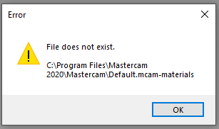
Whenever I add a machine, I get the error shown in the attached image. Did a file get moved? Where do I copy the file back to?
-
I'm trying to get Mastercam to always default to my Desktop when saving a new project. I want to create one folder on my Desktop which contains all the mcam files, solids, NC files, notes, drawings, etc. Apparently I can do this with the Project Manager, but it's default location is \Shared Mastercam 2020\. Every time I open Mastercam and start a new project, it directs me there instead of my Desktop. It's tedious and annoying to have to constantly navigate back to the Desktop to open the folder I've already made at this point. It's a computer; this should be (a) automatic and (b) configurable. Is there a way to point Mastercam in the right direction?
-
Well damn, that's the response I was looking for. Would still be nice if deleting the points in the "Features" list with the keyboard or mouse would work as expected, but this is a good workaround. Thank you.
-
Geometry selection page? Do you mean the entry shown in the attached image? Because that is what I've been using to modify the points, and I'm still getting the error I describe above in my first post. What do you mean by "reselect?" Right click does not give me that option, nor do I see it anywhere.
-
I suspect he was making a joke -- you're right that I didn't mention solid vs wireframe because I didn't think it mattered -- wireframe or solid selection, you'd think deleting points would work the same either way. I am trying to take advantage of some of the new features of Mastercam 2020 by not always taking the time to do the preparation that I used to do with earlier versions, but it looks like I'll need to revert to those methods to compensate for the shortcomings of 2020. Regardless, it was not my intent to upset anyone's day, and I apologize if that's what happened. I appreciate the point that wireframe and solid selection behave differently, and I'll keep an eye out for that in the future.
-
Glad I'm not the only one then... I see now it was using solid arcs as opposed to my usual wireframe points. That's a good distinction. I definitely feel that last part.
-
I do apologize if I came across as harsh -- I spoke out of some frustration that the first response was, "Did you try the thing you already tried?"
-
Please take the time to actually read my post. I clearly state that that didn't work.
-
I'm using the drill toolpath and having an issue deleting specific drill points. I have 20 points selected, but I want to delete the 3rd and 8th points. However, when I delete them, Mastercam instead deletes the 1st and 2nd points. I've tried right clicking on each point and selecting delete; selecting both points, right clicking and selecting delete; and selecting both points and pressing the delete key on my keyboard; selecting each point individually and right clicking delete, selecting each point individually and pressing delete. In all cases, Mastercam will only delete the first two entries. No combination of selecting anything will get the entries I want deleted -- Mastercam appears unable to do anything but delete from the beginning and work it's way down. Even restarting the program or reloading the file has no effect. Has anyone else seen this? My workaround, and it's ridiculous that I even have to do this, is to right click on the points, select "move to top," and then delete them. Then it "works."
-
Surface High Speed (Area Roughing) not cutting to bottom
saltedfish replied to saltedfish's topic in Industrial Forum
Really appreciating the responses here, thank you all so far. @Manofwar: I switched the toolpath type from Area Rough to Optirough so that I could explore the settings you're talking about. I found the Step Up option you were referring to, enabled it, and set it to 10% (the same value as the Step Down). However, I'm still seeing the same behavior as I was in Area Rough (see picture). I'm also not sure why the toolpath is all... wonky like that. Z Depths encompasses the entire depth of the pocket, Skip Pockets is set to 0, @The Chipmaker: Could you reupload those pictures at a higher resolution? I can't make out the text Mystery solved folks: It's a combination of me forgetting the scale of the view and the Step Up. I had .005" on the floor, and when I removed that but had the Step Up enabled as @Manofwar suggested, the toolpath went all the way to the bottom. I just didn't realize the enormous looking gap was just the stock remaining on the floor. Oops. Thanks everyone for their help. Follow up question: what are the pros and cons of optirough vs area rough? Is there any reason to use one over the other?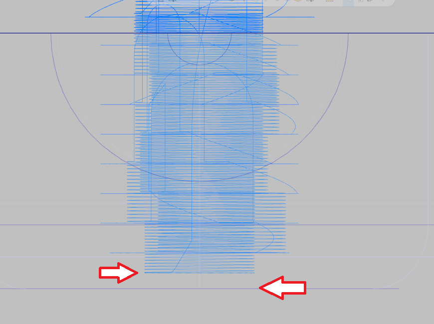
-
Surface High Speed (Area Roughing) not cutting to bottom
saltedfish replied to saltedfish's topic in Industrial Forum
When you say "step up," what value are you referring to? I'm not seeing it anywhere in any of the pages. Is that an option for MC2017?