MatthewMachinist
-
Posts
15 -
Joined
-
Last visited
MatthewMachinist's Achievements
")


-
OK, thanks for the fantastic answers guys, that also explains why the training courses lump 4 and 5 axis stuff together. I think I will forge ahead and do the Mastercam Multiaxis course to get a head start with this. Matt.
-
Hi, I work a 3 axis mill with 4 years experience with Mastercam. I sometimes get to use our 4 axis rotary table, I have so far just used the 2d and 3d toolpaths with a lot of transform rotates. However I am interest in the multiaxis toolpaths, which I know NOTHING about. My question is which of these toolpaths can be used on a 4 axis machine? It seems like a simple question but I have been having trouble finding an answer... I am probably looking in the wrong places. I was considering doing a course on improving my 4 axis skills but it seems every course includes 5 axis as well, which could have its benefits I guess providing the toolpaths also work on a 4 axis machine. Thanks, Matt.
-
Mastercam University - Help needed from a student
MatthewMachinist replied to MatthewMachinist's topic in Educational Forum
Thanks for all the help with this one... I have been able to get this line normal feature to work on several other files... I think I will just redo this project. Matt. -
Mastercam University - Help needed from a student
MatthewMachinist replied to MatthewMachinist's topic in Educational Forum
Thanks Jayson, I have placed the construction plane where it needs to be... is that what you mean by C. Thanks, Matt. -
Mastercam University - Help needed from a student
MatthewMachinist replied to MatthewMachinist's topic in Educational Forum
Ok I gave it a go, I found a reset at "file - options" where you can reset the toolbar? I googled and searched and that was the only reset I could find. I found the config file at C - Mastercam - common - user defaults So I shut mastercam down, did the file extension and it hasn't made any difference. Thanks, Matt. -
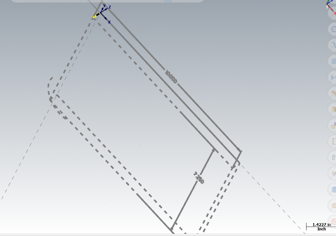
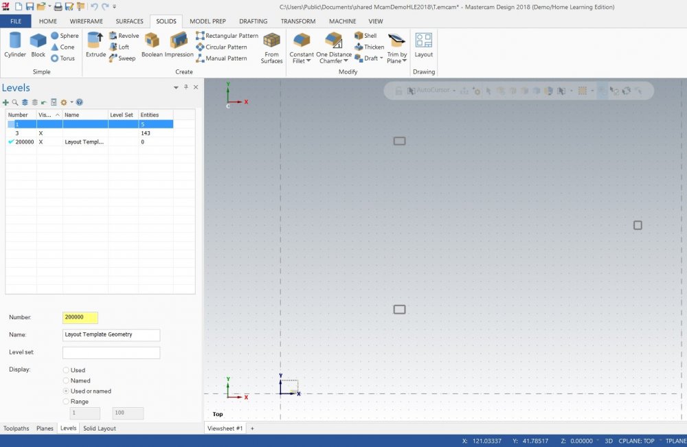
Hello, I have been working at creating blueprints from a very simple model. It is working but the views are outside the template, if you look at the screen shot I uploaded you can see the template is in the bottom left hand corner, small enough that it is hard to see at first glance. I must be missing a step? Also does anyone know the process for creating a pdf from the drawing layout? I am really not sure at all how to actually export a drawing layout. Thanks, Matt.
-
Mastercam University - Help needed from a student
MatthewMachinist replied to MatthewMachinist's topic in Educational Forum
Thanks for the tips radical1, unfortunately they haven't solved the problem. -
Toolpaths, viewsheets and datums
MatthewMachinist replied to MatthewMachinist's topic in Educational Forum
Thanks a million Rekd, I looked everywhere expect toolpaths. -
Mastercam University - Help needed from a student
MatthewMachinist replied to MatthewMachinist's topic in Educational Forum
Thanks for the video, I have just tried doing it exactly as per the video and I am still having the same problem. I have also just found out (if I understand this software correctly) that most people on this forum won't be able to open my student version file? Thanks again, Matt. -
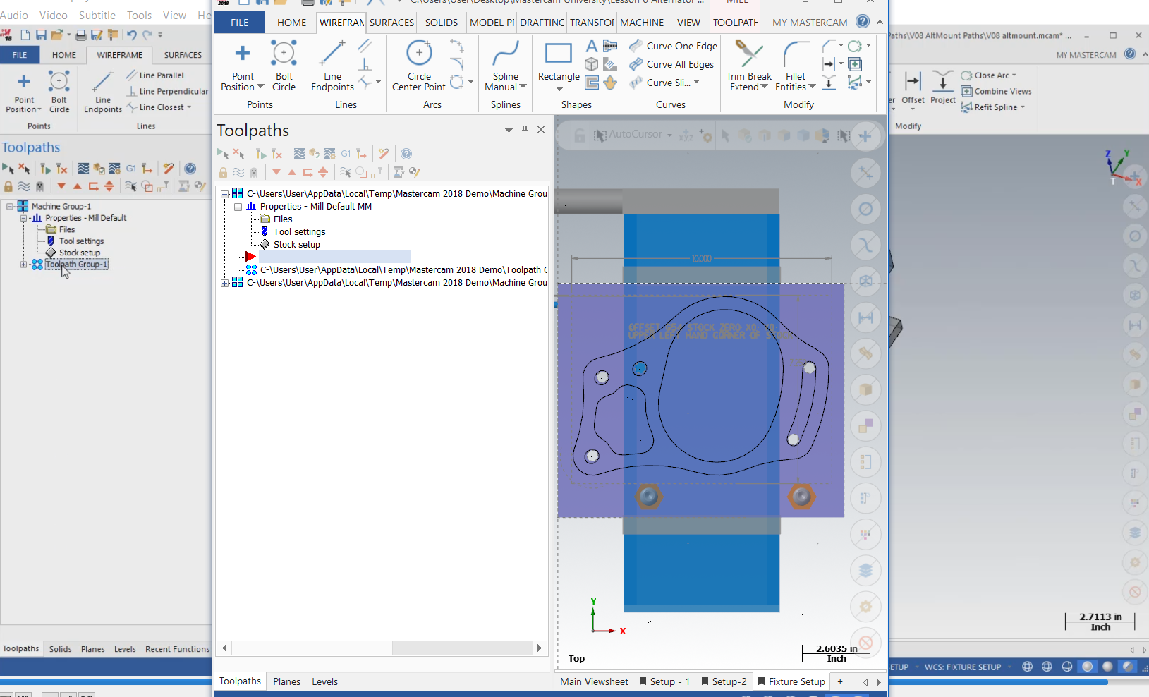
So I though I was making progress with toolpaths but I have hit another brick wall or two. I have finished all of the machining operations on the jig, but my first machining operation failed on the workpiece. I did some problem solving and found that the datum was still set to the corner of the jig not the work stock. So fixing it should be easy. However what has NOT been explained is the relationship between setup sheets and datums. So I tried to solve the problem by setting the wcs, C and T to the top of the stock, which is called work plane however the moment I click on another viewsheet and click back it has defauted back to where is was. So I don't know how to even set the datum where it needs to be? I have tried dragging the gnomon but that doesn't seem to work. Regarding setup sheets... are they meant to correlate to machining operations, if for example my first machining operations are performed on the jig itself in main viewsheet... then should my first toolpath name match the viewsheet? I guess I am asking what is the relationship here. The insturctor has also asked us to setup a viewsheet named setup 2, so presumably the 3rd set of machining operations will happen on this viewsheet? So viewsheets correlate with machining operations? I am also struggling because my stock is a dotted line outline, for some reason my level 100 is the only level that I can't turn off and on, and even if I select the geometry and select the fattest solid line... it still appears as dashed? Lastly my mouse wheel scrolls at about one fourth the rate that the insturctors does, I have tried altering this in windows but that makes my scroll speed insanely fast when I close mastercam. Does anyone know where I can alter the mouse scroll speed setting in mastercam? Thanks, Matt.
-
Ok Thanks for all the help with this one... I am all sorted now everything is working as it should. Cheers, Matt.
-
Mastercam University - Help needed from a student
MatthewMachinist replied to MatthewMachinist's topic in Educational Forum
Lesson 4 Triple Tree.emcam Thanks for helping, Matt. -
Hi, I am currently working on Mastercam University Mill Design and Toolpaths and I am working on the creating alternator mount fixture. I am up to creating toolpaths, I followed the instructions and selected all of the required tools, however when I clicked the green tick a screen appeared asking if I wanted to save the tools to my library, the instructors screen didn't come up with the same message so I flipped a coin and said yes. Now my toolpath menu is completely different than the nicely named and organised one my instructor had. I have been trying to click on these items to work out which one represents the tool list I just created and basically I don't know where to begin etc. Should I have clicked to add the tools to my library? Can I rename these files to be more organised? Whats up with the dark color triangle? Which one is the tool list I just created? How can I tell if it loaded properly? I apologize for all the questions but I am finding with this course that the instructor says what to do (at warp speed), but never why, how, what if etc. So I am struggling with a steep learning curve and this is my first time doing this type of operation. I wish the instructional video actually covered what these file options and settings represent.

-
Mastercam University - Help needed from a student
MatthewMachinist replied to MatthewMachinist's topic in Educational Forum
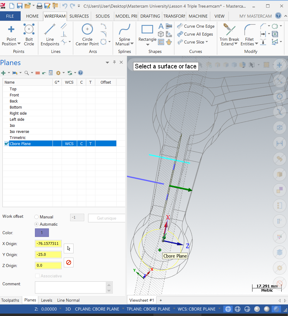
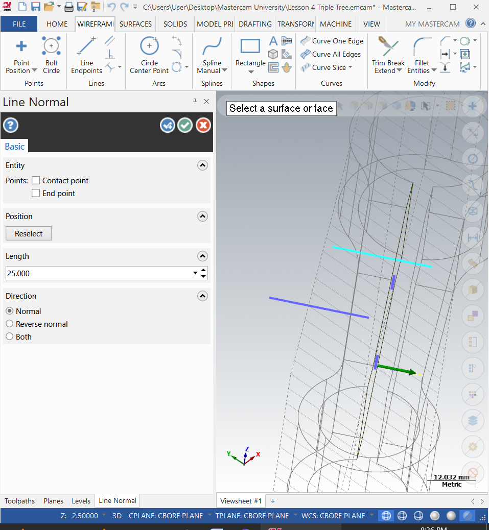
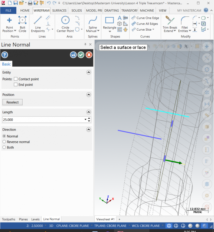
Thanks for helping me understand levels, it still seems weird to me that a plane can be created on a level but it is somehow independent from level it was created on. I guess I have spent too much time using design trees on SW. I have gone through all my work again and my problem remains, I can't stress enough that I am meticulously following the instructions provided by the instructor, however it is problematic keeping up with the course because the instructor says what he is doing, but the hows, whys and what mouse button he is clicking is often not said. Anyway the face has been selected and the plane is where it should be. Here are some more photos...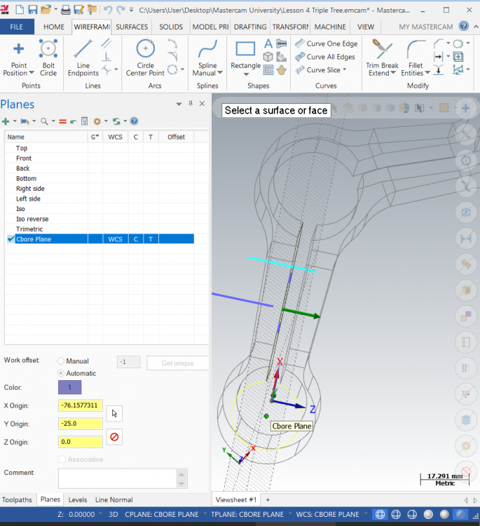

-
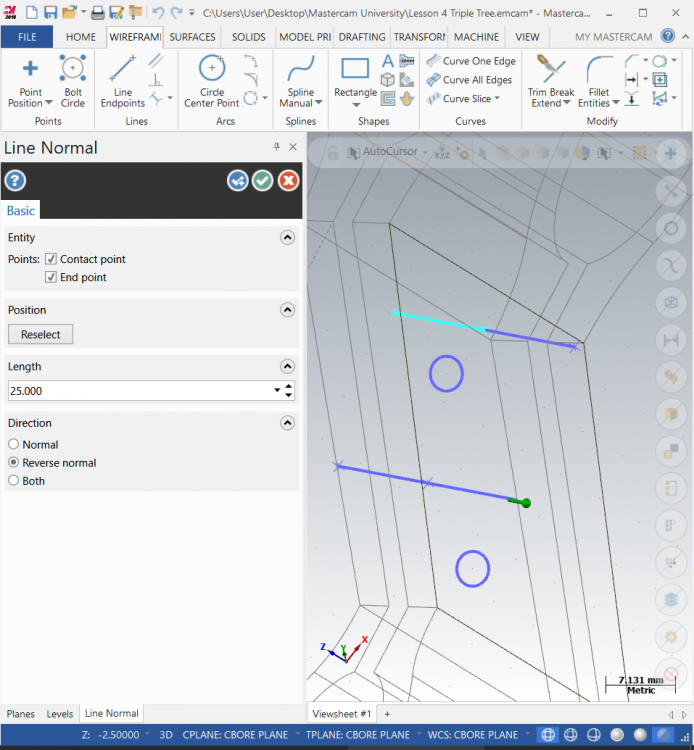
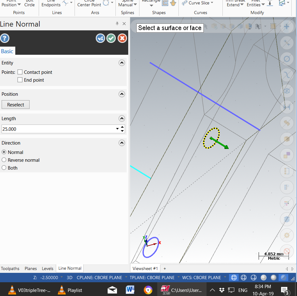
Hello all, My name is Matt, I coming from an Engineering/ Machining background. I am brand new to Mastercam, but I have professional experience with Solidworks and Autocad (2d only with autocad). I am currently doing the Mill Design and Tool paths course using the Mastercam student version. I have been having quite a bit of trouble here and there because the videos were created with an older version, however I have been able to find solutions to most problems with experimenting, googling etc. I am having trouble with part 4 Triple Tree, I am required to draw lines using the line normal feature. I select the hole centre and click and the line appears nowhere near the centre I selected. I have tried re doing my work from the start 3 times, making sure I follow every step I have made sure I have set up the correct plane I have set up the levels as instructed. As a newbie I do have some additional questions I am hoping I can get help with, Because I am studying on the weekends my local distributor is closed whenever I need help, when I signed up for the course it was never explained to me who my "teacher" or contact person is... is it this forum? Coming from a Solidworks background it has been a long time since I used levels, I used to use them in Autocad 2d to define different types of geometry for basic engineering drawings. I am struggling to understand levels in a 3d sense, for example in this tutorial the tutor has asked us to create a new level and a new plane to draw these holes, I am struggling to understand why I need both. Why do the holes need a level at all. I guess I am asking for a precise definition of what a level is in mastercam. Once I have a definition for a level then I can understand it. I am also not sure (it has not been explained) how levels relate to datums when I enter co ordinates to locate features. Note - in the photo I have clicked reverse normal to highlight where the line is snapping to. The snap location appears random. Thanks for any help you can give, I am hoping I have just missed something simple. Matt.