KevinMSC
-
Posts
11 -
Joined
-
Last visited
KevinMSC's Achievements
")
Newbie (1/14)
0
Reputation
-
So heres what is really throwing me off. If I rotate the tool plane in a direction that changes the Z it will post out and run fine but if I rotate around Z like in my example above it will not rotate. Attached is a picture of the rotation that worked along with the posted code, G00 G17 G20 G40 G80 G90 G91 G28 Z0. G28 X0. Y0. M79 M11 G90 A0. C0. N1 T1 (0.75 FLAT ENDMILL) M06 G54 G17 G90 G00 A-90. C-180. G05 P10000 G68.2 X0. Y0. Z0. I0. J90. K0. G53.1 M78 M10 X-10.25 Y10.8385 S448 M03 G43 H1 Z10.25 G94 Z8.25 G01 Z7.25 F25. Y10.0885 F5.99 G03 X-9.5 Y9.3385 I.75 J0. G01 X9.5 G03 X10.25 Y10.0885 I0. J.75 G01 Y10.8385 Z8.25 F50. G00 Z10.25 M05 G69 G05 P0 G91 G28 Z0. G28 X0. Y0.
-
Hey thanks for the reply. So I am using all of my rotational planes from a single point that is my G54. When I try and run this code on our machine it will run it but it will not rotate the C axis it just cuts as it would if the G68.2 was not there. I have tried to contact Methods a few times for OKK support but I guess they are still learning about the machines because it usually didn't lead to any answers to my questions.
-
Hi, I was wondering of someone could help me out with the coding of G68.2 in mastercam. So I am currently trying to machine a part on an OKK table-table machine that the back side of the part sits just outside of the machining area. My plan was to machine half the part then rotate the table so the back is in the front and accessible by the cuter. So my G54 is set to the center of rotation on the A and C axis, then I have my second Rotated coordinate system in the same location just rotated around Z at 180 deg. When I create any tool paths with this rotated coordinate system it does not actually rotate anything A and C stay at 0 instead of posting A0 C180. However if I do the same process and rotate the coordinate system around the A axis 90 deg it will and post A90 and C0 which would be correct. If anyone knew what I was doing wrong with the 180 degree rotation I would appreciate the help. I posted Pics of my 2 coordinate systems and the posted code. Thanks for any help I can get. G00 G17 G20 G40 G80 G90 G91 G28 Z0. G28 X0. Y0. M79 M11 G90 A0. C0. N1 T1 (0.75 FLAT ENDMILL) M06 G54 G17 G90 G00 A0. C0. G05 P10000 G68.2 X0. Y0. Z0. I180. J0. K0. G53.1 M78 M10 X-10.325 Y.1874 S448 M03 G43 H1 Z10.9679 G94 Z9.4679 G01 Z8.9679 F25. X9.95 F5.99 Y-.3991 X-9.95 Y-.9856 X9.95 Y-1.5722 X-9.95 Y-2.1587 X9.95 Y-2.7452 X-9.95 Y-3.3317 X9.95 Y-3.9183 X-9.95 Y-4.5048 X9.95 Y-5.0913 X-9.95 Y-5.6778 X9.95 Y-6.2644 X-9.95 Y-6.8509 X9.95 Y-7.4374 X-10.325 G00 Z10.9679 M05 G69 G05 P0 G91 G28 Z0. G28 X0. Y0. M79 M11 A0. C0. M78 M10 M30
-
I was wondering if anyone who has experience with G68.2 would be able to figure out why my posted code keeps throwing up "5462 illegal command in G68.2". I tried moving around my G54.2 P1 and the G05 P10000 commands but I am still getting the error. I posted the code below. I appreciate any help I can get. G00 G17 G20 G40 G80 G90 G91 G28 Z0. G28 X0. Y0. M79 M11 G90 A0. C0. N1 T1 (0.5 FLAT ENDMILL) M06 G54 G17 G90 G00 A-90. C0. G05 P10000 G54.2 P1 G68.2 X0. Y0. Z0. I180. J90. K0. G53.1 M78 M10 X-1.95 Y4.6887 S2139 M03 G43 H1 Z6.475 G94 Z3.475 G01 Z.475 F25. Y4.1887 F32.09 G03 X-1.45 Y3.6888 I.5 J0. G01 X1.45 G03 X1.95 Y4.1887 I0. J.4999 G01 Y4.6887 Z3.475 F50. G00 Z6.475 G69 G53.1 G49 G54.2 P0 G05 P0 M05 G91 G28 Z0. G28 X0. Y0. M79 M11 A0. C0. M78 M10 M30 %
-
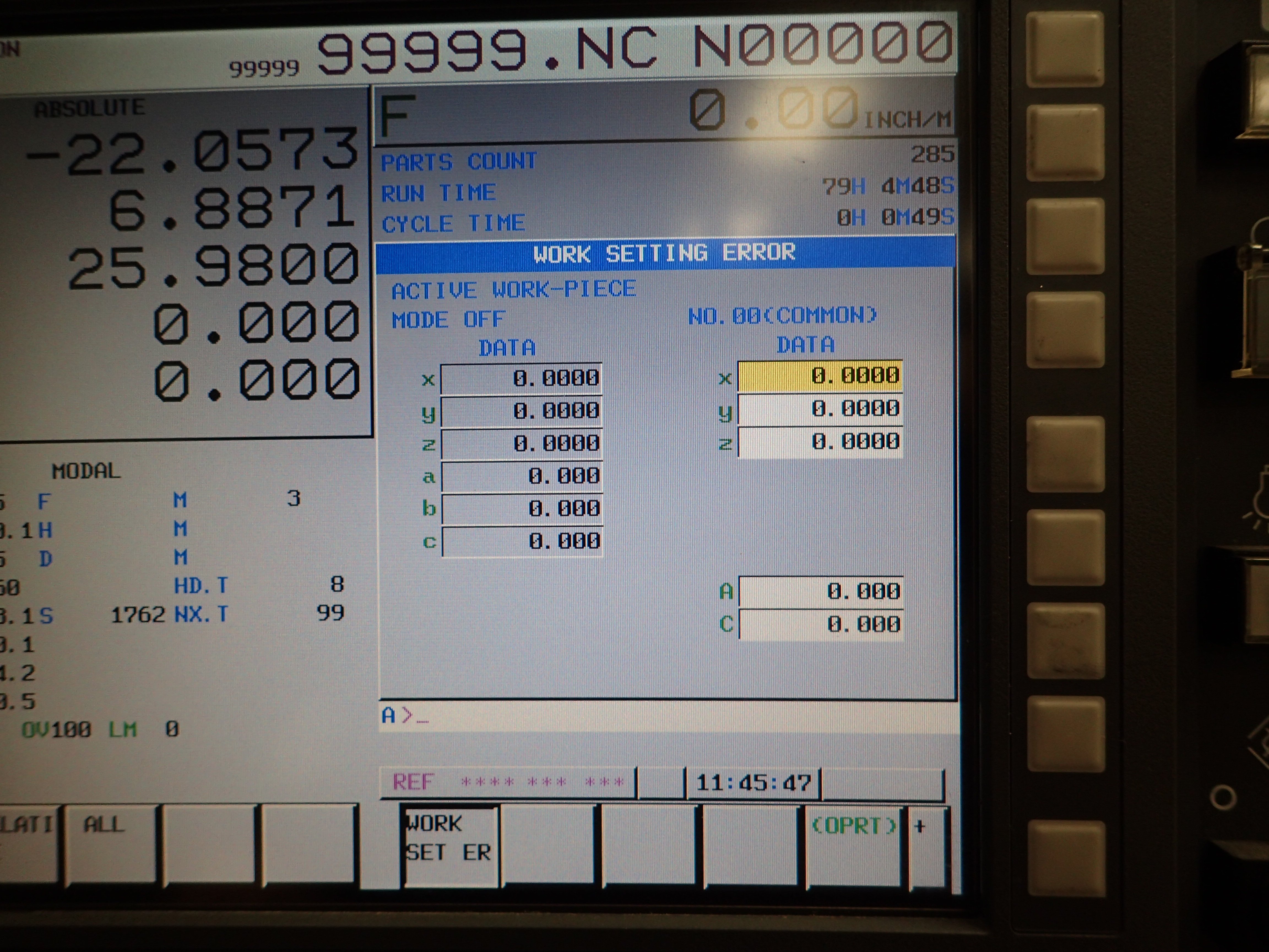
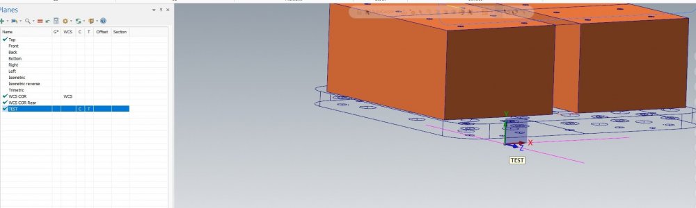
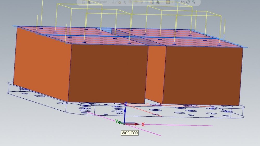
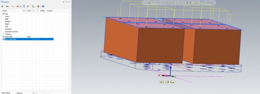
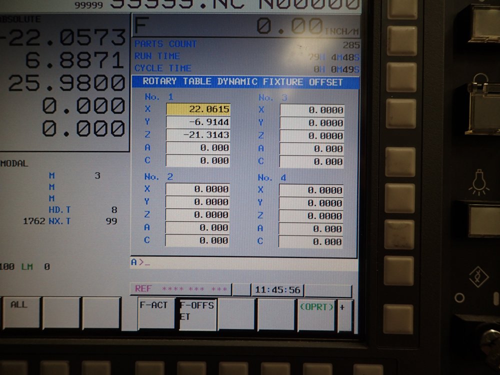
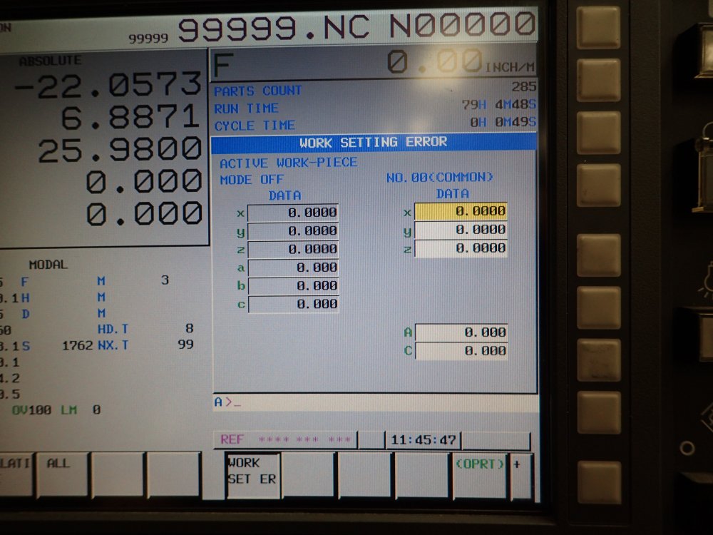
Thanks for all the replys its all super helpful info. So what I have gathered so far is this... Rotary Dynamic Fixture Offset (G52.2) is used for 3+2 axis work and it can not be combined with G43.4 (TPC) but it can be combined with Tilted Work Plane Comp (G68.2). In order to use simultaneous 5 axis machining we would use Workpiece setting error comp (G54.4) and this can be used combined with G43.4 (TCP). So all of this has raised a few more questions about setting up the work piece and translating our Mastercam WCS to the machine. For Rotary Dynamic Offset and work piece error compensation I was under the impression that we would set our G54 to the true machine center of rotation for X Y Z (we have a trunnion table). Then for the fixture offsets we will set those to where the part is located on the table which is not at the center of rotation. Then in Mastercam I can put my WCS on the model that corresponds to where I set the offset of either G54.2 or G54.4 depending on our operations. I attached some pictures of our 2 offset screens on our Fanuc controller. Thanks again for all the help! ).
-
So I tried moving the G54.2 to right after the G55 and I still got the same error when it hit the G43.4 line. If I run the machine simulation on the Fanuc controller it will play through the entire thing without any errors... Thanks for the replys. G00 G17 G20 G40 G80 G90 G91 G28 Z0. G28 X0. Y0. M79 M11 G90 A0. C0. N1 (TOOLPATH - FINISH5) (STOCK LEFT ON DRIVE SURFS = 0.) T8 (0.2506 BULL-NOSED ENDMILL) M06 G55 G17 G90 G54.2 P1 G00 A-90. C0. G05 P10000 G43.4 H8 X0. Y-8.0332 Z5.425 S1762 M03 G94 Z1.525 G01 Z1.425 F13.66 G93 X-.0009 C2.111 F277.29
-
Hi, We have recently added Dynamic Fixture Offset to our OKK VP600 machine and I am having trouble getting our code to work. I have tried going through our OKK distributor and MasterCam post distributor but as of now no one has known what the issue is. Whenever I run a code that has a G54.2 in it I get an error that says "Illegal command in the G43.4/G43.5" If I take the G54.2 line out the will run but then it is not accounting for the offset in G54.2. I posted a sample of our code below, Id appreciate it if anyone could take a look and see if they know what is missing or in the wrong place. Thank you. (T8 - 0.2506 BULL-NOSED ENDMILL - H8 - D8 - D0.2502" - R0.0300") (G10 G90 L21 P1 X-0.0000 Y-0.0000 Z-0.0000 B-0.000 C-0.000) G00 G17 G20 G40 G80 G90 G54.2 P1 G53 Z0. G91 G28 Z0. G28 X0. Y0. M79 M11 G90 A0. C0. N1 (TOOLPATH - FINISH5) (STOCK LEFT ON DRIVE SURFS = 0.) T8 (0.2506 BULL-NOSED ENDMILL) M06 G55 G17 G90 G00 A-90. C0. G05 P10000 G43.4 H8 X0. Y-8.0332 Z5.425 S1762 M03 G94 Z1.525 G01 Z1.425 F13.66 G93 X-.0009 C2.111 F277.29 X-.0015 Z1.4251 C4.219 F279.54 X-.0018 C6.325 F281.46 Z1.4252 C8.425 F282.94 X-.0016 Z1.4253 C10.52 F285.35 X-.0013 C12.608 F286.69
-
That was how our post processor posted the code out. I was just reading up on using FPM verses inverse time. Ill bring this up when I talk to our post processor developer about our other issues. Thanks for the info
-
This post processor was bought for this machine through our mastercam distributor. I currently have a service ticket in with them but still haven't heard anything. While I am waiting I figured i could post here to see if I could learn anymore info and if it was actually the post processor or if I was doing something wrong. Thanks for the reply!
-
I recently started trying to perform multi axis operations on our OKK VP600 5axis. Up until this point all of our 3 axis operations worked fine with our mastercam 19 post processor. Earlier I tried to run a simple multi surface code that when I ran it threw up error"PS5421 illegal command in G43.4/G43.5" on our Fanuc series 310is-model A5 controller. The simulation in master cam went fine and the simulation on the machine went fine. I've never had any issues running multiaxis codes on our other machines which have a rotating head as opposed to this machine which has a trunnion table. I posted a sample of my code below. I know this has something to do with TCP but I am unsure how to fix this. G00 G17 G20 G40 G80 G90 G91 G28 Z0. G28 X0. Y0. M79 M11 G90 A0. C0. N1 T3 (0.5 SPHERICAL / BALL-NOSED ENDMILL) M06 G54 G17 G90 G00 A-90. C90. G43.4 H3 X0. Y-6.6062 Z5.85 S2139 M03 G94 G05 P10000 Z3.85 G01 Z1.85 F25. G93 C92.102 F472.46 C94.282 F456.31 C96.541 F440.02 C98.882 F423.9 Another code I tried to run used a rotated machining plane when I tried to run this code I got the error "0010 Improper G Code" when it hit the line with G68.2 G00 G17 G20 G40 G80 G90 G91 G28 Z0. G28 X0. Y0. M79 M11 G90 A0. C0. N1 T1 (1/2 FLAT ENDMILL) M06 G54 G17 G90 G00 A-90. C-90. G68.2 X0. Y0. Z0. I90. J90. K0. G53.1 M78 M10 X-10.8459 Y.175 S2139 M03 G43 H1 Z10.1609 G94 G05 P10000 Z1.5625 G01 Z1.2157 F6.42 X-10.348 Y.2208 F32.09 G03 X-9.8958 Y.7645 I-.0458 J.4979 I am really looking for any help I can get right now. I am unsure if it is something I am doing wrong with the machine set up since this is our first trunnion table machine or if our post processor needs to be updated. Thank You!
-
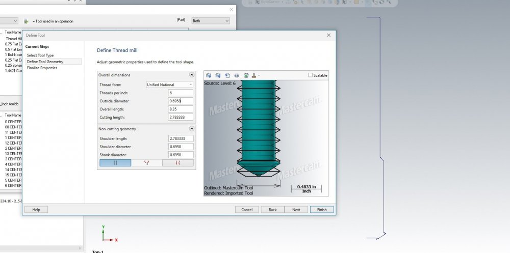
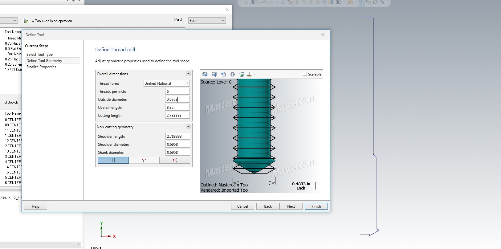
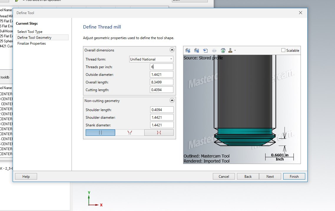
This is my first time trying to create a custom thread mill in mastercam 19. I followed some previous forms/tutorials and am still having issues. I am trying to get it to create a single point insert thread mill (Kennemetal 5593134). I have tried 2 ways so far first I tried importing the tool file that i downloaded from kennametals NOVO app which gave me the correct geometry however the threads that mastercam was overlaying did not line up. Second I brought in a DXF of the tool and sketched out half the profile then tried to create a tool with that but it came up with a different geometry and the threads did not line up again. I attached some pictures as well as the stp file of the tool. I would appreciate any help I can get on here especially knowing if this tool is even possible to use with mastercam thread mill tool path. Thanks! Thread Mill.DXF KTMDUED144L512Z3.STP KTMDUED144L512Z3 Tool Outline.mcam