ajmer
-
Posts
500 -
Joined
-
Last visited
Content Type
Profiles
Forums
Downloads
Store
eMastercam Wiki
Blogs
Gallery
Events
Everything posted by ajmer
-
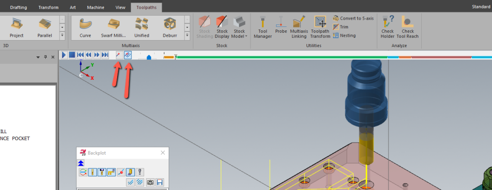
the only way to do this is to save the deburr operation backplot as geometry then do a C axis face contour on that geometry then the post will post as C and X or if using G112 it will output correctly
-
What will be the best 5th Axis Toolpaths for this part?
ajmer replied to XLAZY-'s topic in Industrial Forum
i would use somethingajmer_ihs_emastercam file.zip like this -
yeah waterline works well its the opti rough that has a hard time keeping down
-
Problem with using "Curve on all edges" with 2024
ajmer replied to Camelot's topic in Industrial Forum
make sure 2d/3d is set just in case it is set to 2d and projecting geometry to a z value -
Posting 2 different B0 machining operations, no rotation commands.
ajmer replied to JB7280's topic in Industrial Forum
i used an mpmaster i had i changed this search for and uncomment this line # sav_rot_on_x = rot_on_x #Uncomment this line to output rotary axis value even when it's not used then at the end of ptlchg0$ i added a pfcout on that line ptlchg0$ #Call from NCI null tool change (tool number repeats) was this else, [ pbld, n$, sgabsinc, [if not(index), pwcs], pfxout, pfyout, pfzout, pcout, e$ ] ] i changed to else, [ pbld, n$, sgabsinc, [if not(index), pwcs], pfcout, pfxout, pfyout, pfzout, pcout, e$ ] ] gave me this output N5 G00 G17 G20 G40 G80 G90 N10 G91 G28 Z0. N15 (COMPENSATION TYPE - COMPUTER) N20 T239 M06 ( 1/2 FLAT ENDMILL) N25 (MAX - Z.25) N30 (MIN - Z0.) N35 G00 G17 G90 G54 B0. X-.25 Y.5 S1069 M03 N40 G43 H239 Z.25 N45 Z.2 N50 G94 G01 Z0. F6.42 N55 X-.75 N60 G03 X-1.25 Y0. I0. J-.5 N65 X1.25 I1.25 J0. N70 X-1.25 I-1.25 J0. N75 X-.75 Y-.5 I.5 J0. N80 G01 X-.25 N85 Z.2 N90 G00 Z.25 N95 G55 B0. X-.25 Y.5 Z.25 N100 Z.2 N105 G01 Z0. N110 X-.75 N115 G03 X-1.25 Y0. I0. J-.5 N120 X1.25 I1.25 J0. N125 X-1.25 I-1.25 J0. N130 X-.75 Y-.5 I.5 J0. N135 G01 X-.25 N140 Z.2 N145 G00 Z.25 N150 M05 N155 G91 G28 Z0. N160 G28 Y0. B0 -
no problem really not sure why you would ever have that enabled
-
its this
-
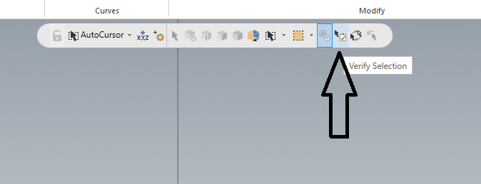
there is an exact mode somewhere in the parameters try that its prob set to approximate
-
i just ctrl clicked the wall of the holes, not the edges but the wall and it picks all the holes with the same dia
-
i added a hole that is shallower than the rest and it worked correctly see file part.mcam
-
+10000000000000000000000
-
this works aswell
-
this might explain things
-
here is a file using old school ruled ajmer_ihs_test.emcam
-
i think this is what Ron was mentioning spiral_ajmer_ihs_IM42333.mcam
-
if you dont have multi axis you could use rollidie its a bit wonky as you cannot really change parameters, it doenst regen correctly and it doesnt have lead in/out either if you want to make changes do the toolpath again its a chook ajmer_ihs_IM42333.mcam
-
Warning from Vericut regarding Arc start and end points.
ajmer replied to [email protected]'s topic in Industrial Forum
i think that your total tolerance is too big not sure if that is what is causing these issues but try changing it to 0.002" or even 0.001" and run it thru vericut adn see if the same errors happen -
try project see attached file !!oops looks like it does the same thing as 3d contour in the vertical area ajmer_ihs_raster test.mcam
-
try this surface rough flowline it will give you the added cuts ajmer_ihs_CHAMFER (1).mcam
-
TRY THIS YOU WILL NEED TO SET TOOL TO CENTER OF BALL FOR HEIGHT OFFSET THOUGH AJMER_IHS_430-00581, REV-D, MILLWORK 1.mcam
-
Cimco Edit 8 not starting due to missing MSVCR100.dll
ajmer replied to [email protected]'s topic in Industrial Forum
these need to be installed https://www.microsoft.com/en-us/download/details.aspx?id=26999 -
check if machine is set to inch/min 0.007"/min looks like it is not moving
-
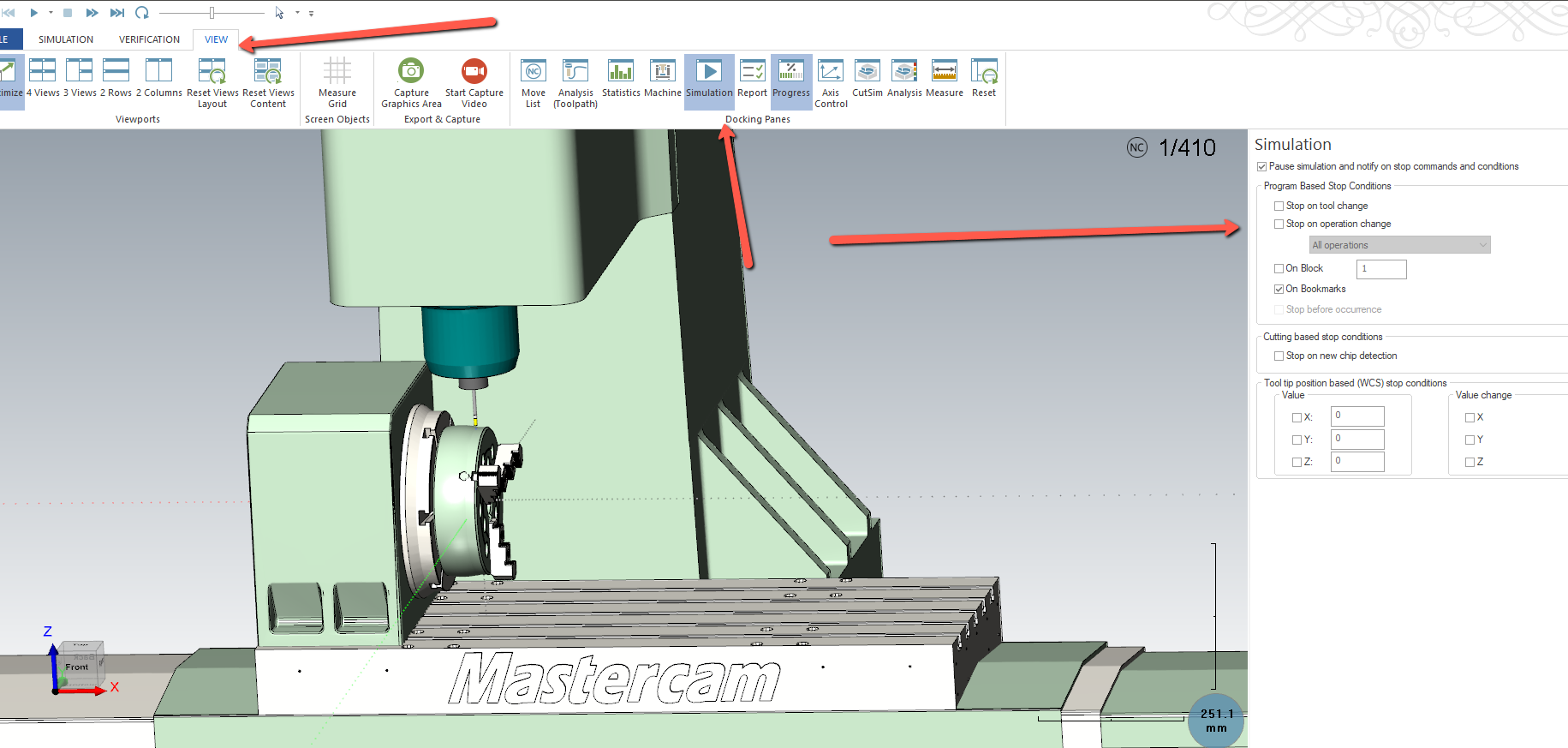
Where to select stop condition options in Machine Simulation
ajmer replied to [email protected]'s topic in Industrial Forum
click the view tab turn on the simulation panel its in there
-
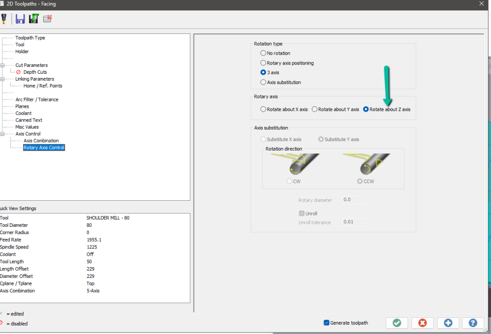
make sure you have these set correctly
-
not sure if this helps you or not but in 2023 you can bump solids see video here https://www.screencast.com/t/4xtkjRBM9kNt