Steelab
-
Posts
41 -
Joined
-
Last visited
-
Days Won
1
Content Type
Profiles
Forums
Downloads
Store
eMastercam Wiki
Blogs
Gallery
Events
Everything posted by Steelab
-
MC 2023 opening Solidworks assembly ignores configuration selected
Steelab replied to gargodude's topic in Industrial Forum
I've been seeing very similar issues with opening SW parts with multiple configurations, now it just opens the config that I had open in SW without asking what config I want. It also gives me an error when trying to open a parasolid saved from that config... -
Given your description I think a simple Contour toolpath can accomplish the single depth, multiple pass, with a retract between passes. Circle mill without roughing is basically just a contour anyway... I think you need to turn on roughing, helical entry, and depth cuts to get circle mill to retract between depths.
-
Click in the Verification tab, zoom to the area you want to see, then click "Apply Refine" This will temporarily eliminate the part of the model that isn't in the current view. Edit: This is in the Machine Simulation Verify, not the Simulator Verify... it's the one that can be accessed using Ctrl+Shift+M
-
I found another weird thing to be cautious about with the new groups: Be sure to save your viewsheet before adding it to an existing group. if you add a new viewsheet to a group before saving the viewsheet it will copy all viewsheets from that group outside of the group but you won't be able to delete the ones that aren't in the group without deleting the ones in the group. very strange but not an issue as long as you save your viewsheet before adding it to an existing group.
-
I think that's more of a windows setting than a Mastercam one. Right click on the older mastercam file> Open with> Choose another app> If you don't see the newest version of Mastercam click "More apps" scroll down and click "look for another app on this PC"> navigate to the Mastercam.exe in the newest Mastercam folder found in your program files folder. Repeat this with a file from each of the older versions and you'll see the files icon update to the newest version.
- 1 reply
-
- 1
-

-
My background is set to black and I don't seem to have this problem, maybe try messing with the DPI setting or zooming in on your origin. When in the window where you select "Manually trace bitmap image" look at the image size listed under the "Resolution DPI" selection drop down, if the size seems very small change the dpi to a lower value... There will not be any entities added to the screen statistics until you manually draw geometry over the image. What file type are you using?
-
Where in the Machine Definition can this default view be added?
-
Our Router is longer on the Y axis than on the X axis, so I have to rotate 90deg to get the view oriented for the best view for our setup sheets. Is there a way to rotate the default Top GView so it will orient the way I want when I press my Top View Hotkey? Not a huge deal but I have to go through the trouble every time to rotate 90deg and make a viewsheet so I can quickly access it...
-
I get the same results using 0 or 360. 180 will set it to 0 or 180...
-
Pitch in your little gems that make mcam life easier
Steelab replied to jlw™'s topic in Industrial Forum
Posting multiple toolpath groups within one machine group with unique names and eliminate the Partial NCI output file prompt that asks if you want to post all... In Configuration>Toolpath Manager>NC File select [Toolpath group name] If you're copying toolpath groups you'll need to right click the toolpath group>edit selected operation>change NC file name to match your new(copied) toolpath group name. Select the entire machine group and post and it will automatically post separate programs for each toolpath group with the names of the toolpath group as your .CNC file name. -
Not sure if it's the same in X8 but a few things to try are: In your example of putting radius on sharp corners do you have trim selected or is it leaving the sharp as well as adding the fillet? Select trim entities to delete the sharp corner automatically. Also from your example, if all of your external corners are getting the same radius you can probably just address this in your toolpath by changing your external corner break radius in cut parameters. Make sure you have CPlane selected in chaining instead of 3d and make sure your WCS, Construction, and Tool plane are set to the same plane as your wireframe geometry. Sometimes if you are changing views your C and T will follow your G view and if you start chaining it will think you are trying to chain on a perpendicular plane. There's a setting to make it so G doesn't follow C and T but I think it does by default... Try setting your z depth to the same depth as your wireframe and set it to 2d instead of 3d. Again, not sure if any of this helps because I'm using 2021...
-
If a part is coming in with wireframe and solid I usually select all wireframe using the quick mask and delete it all because there is so much wireframe that is useless and just slows things down. I'll usually create a level and viewsheet for solids and one(or more) for wireframe so I can toggle quickly. I'll also usually change wireframe color as I create different wireframe for different operations. I rarely use curve on ALL for an entire model anymore because it makes so much wireframe geom that I won't end up using and with big parts it can slow things down to the point that it's faster to use curve on ONE edge and select what I'll use or curve on ALL and only select one face. Quick masks are great for selecting wireframe as shown above. I've also used Invert selection for similar situations where I want to select most of the entities, just pick what you DONT want selected and click Invert selection to get everything that was not selected.
-
Correction: If you copy toolpath groups you will need to edit the NC file name of the copied operations to allow the posted code to be saved as the Toolpath group name.
-
...Aparently the System Config setting doesn't work if there are multiple Toolpath group names, it only assigns the first one... ugh...
-
I think I (finally) figured out a good solution for this. In System Configuration > Toolpath Manager > NC File I check the box to assign the Toolpath group name. In my Active Report I have the file path to the Mcam file using MCXFILE-LONG and have a separate box that lists the NC File name using TOOLPATH-GROUP-NAME I think that will work for my purpose... Almost done setting up a super simple setup sheet on one page so the operator can see relevant information.
-
I'm making a custom setup sheet and wondering if there is a Data Field value that will list the file location of the .CNC file posted to our server. Like MCXFILE-LONG lists the file path for the Mastercam part file. This is for the operator so they can find the .CNC files that I post to our server. For some files I can just save the .CNC file as the same name as the .mcam file and use MCXFILE-LONG but often I have multiple nests or several different Toolpath Groups with different .CNC files...
-
Importing requires Right click>Import>Click contour>add>ok>cancel>geometry>add>click chain>enter>refresh Still faster to just do it the way I have it set up and pick the tool assembly. I'm trying to save time when I have lots of this stuff to get done fast. I have macros set up so I don't need to move the mouse around to click things, I press a macro button on my mouse, click the chain, hit enter and click the green check then hit another macro on my mouse to post the code and I'm done. Once I open the file and position the geometry where I want it it's 5 clicks to have a posted code or 9 if I want to update the tool assembly.
-
really any additional steps like this would be slower than just going in and picking the tool assembly that I want to have set as default. To complete the whole process I click a macro button on my g600 mouse, click the chain, hit enter, then click the green check mark. To complete the whole process if I want the tool assembly to be correct I click a macro button on my g600 mouse, click the chain, hit enter, click tool, click select library tool, click on the tool assembly, hit enter, then click the green check mark. It's half the clicks every time if I don't pick the tool assembly and I'm just trying to figure out if there's a way to make the operation defaults save with a tool assembly...
-
I've gone into my operation defaults and edited the default parameters of the 2d contour toolpath so all of the settings are the way I usually need them(tool #, tool diameter, feed and speed, cut parameters, breakthrough, linking parameters, arc filter, planes) and they all post out ok but the tool, tool holder, and tool projection all change from what I have set in the operation defaults so any simulation is not accurate.
-
I've set my Operation Defaults and they post the way I want but the Tool, Holder, and Tool Projection that I've assigned in the Operation Defaults don't come through automatically. Is there a way to make this work? To clarify: most of what I do is just a 2d contour toolpath using the same tool, holder, and material. I have it set so all I have to do is click the geometry and hit enter and post the code, but I want to see the correct tool, holder and projection without picking the tool assembly each time. I laterally click a button on my mouse set as a macro for contour and click the chain and hit enter and I'm done but the damn tool changes to a 1in overall length tool that doesn't exist in my default library and it automatically assigns the "default" tool holder which as far as I can tell can't be changed.
-
Is there a toolpath that can help to sharpen corners using a tapered endmill and 5 axis positioning? Basically like a swarf mill on both sides of an interior corner where the tip of the tapered endmill finds the sharp corner and the cutting edge finds the two vertical surfaces of the corner. I guess this would be similar to the engraving toolpath that walks up the corners of the geometry to make a sharp on the surface but tilted using 5 axis so you can get vertical walls.
-
Pitch in your little gems that make mcam life easier
Steelab replied to jlw™'s topic in Industrial Forum
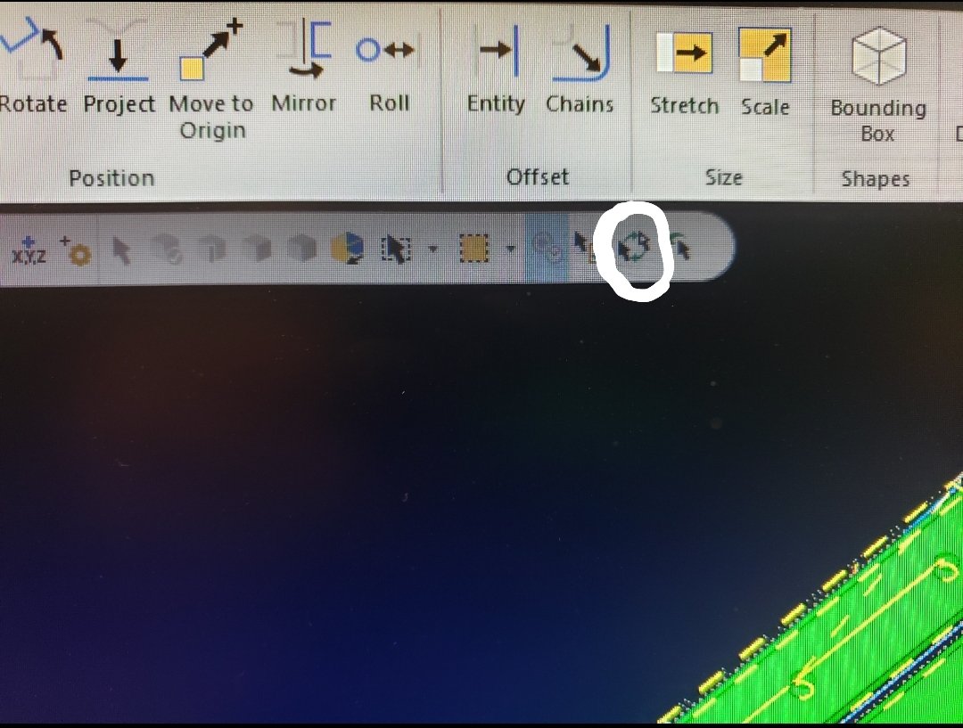
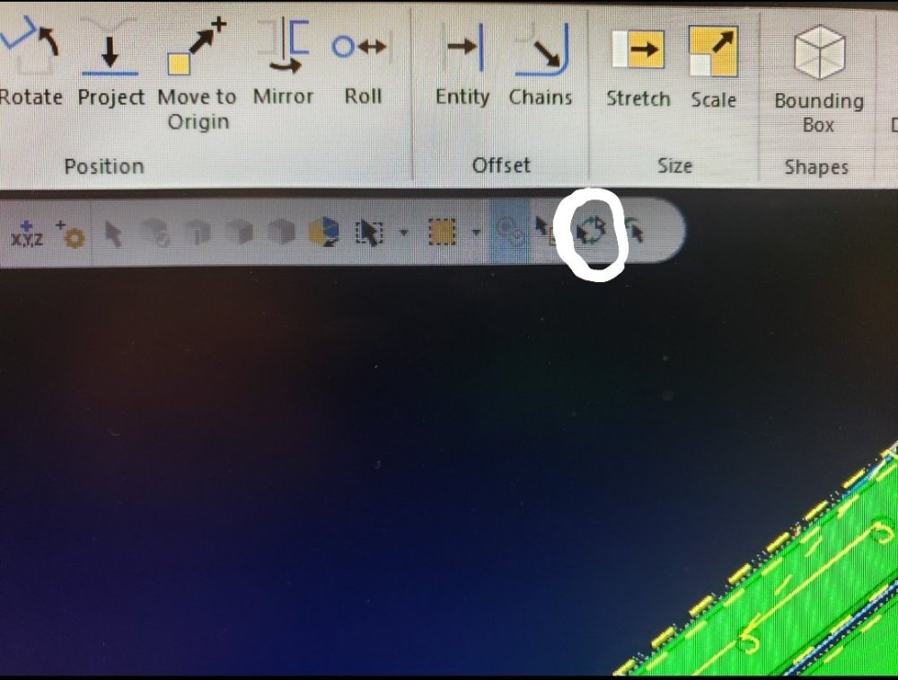
I just stumbled upon a useful hotkey that I was unaware of: When using Dynamic Move I accidentally hit my select all hotkey and noticed that when in dynamic move [Ctrl]+A toggles between part and gnomon movement so I no longer need to mouse click the icon located to the lower left of the gnomon to toggle. -
Regarding ATP I'm trying to get set up to generate toolpaths for our Router using ATP. I've run into a wall when it comes to the necessary XML files , I tried to follow some tutorials but I always get errors...
-
I'm looking to dive deeper into Mastercam. Specifically Automatic Toolpathing, custom setup sheets, and Post Processor editing, Where do I start? What prerequisites are there? What programs do I need to view and edit the file types involved? I've been a CNC programmer and operator for close to 20 years but have only been using Mastercam for about 2 years and am itching to learn more...
-
Set rotation to 0 if you want it to rotate 0 degrees.