MZA2492
-
Posts
7 -
Joined
-
Last visited
MZA2492's Achievements
")
Newbie (1/14)
1
Reputation
-
+1 on Esprit. Programmed Nakumura 3 turret lathes and 2 spindles with ease and I am a native Mastercam user. Esprit does have a back plot option and verification just like mastercam, the interface of the software however is outdated. It seems mastercam over complicates millturn
-
Has anyone tried ice chucking aluminum honeycomb (the kind that iswithout the layered bonded). if so, what is the procedure and fixturing methods once it’s a solid block of ice. Need some tips here please. we are getting complex honeycomb jobs that have a lot of features I’m thinking that tape won’t be good enough
-
 MZA2492 changed their profile photo
 -
Pitch in your little gems that make mcam life easier
MZA2492 replied to jlw™'s topic in Industrial Forum
My top tricks that helps me the most: -levels,isolate basic wireframe or surface geometry to drive 5 axis Toolpaths -Dynamic X form to align the part in space to any WCS of your choice -saving STLs after OP1, loading the STL as OP2 stock in a different machine groups. Personally I don’t use stock models takes too long generating every change, I’ll use optirest if I need to pick out excess stock -Creating a tool library and holder library with your shops tools in the shop and named the mfg etc for common jobs -translating toolpaths, export/import toolpath for future similar work -add remove features of solids, So many tricks and still learning. -
Hosed myself on WCS plane, hopefully for the last time
MZA2492 replied to nperry's topic in Industrial Forum
I always name my main WCS such as OP1 or OP2 and in the planes lock page, input 0 to lock it as G54. Before I post any toolpaths, visually scan each toolpath path and look for WCS: “Name of Main WCS Plane”. you can be 100% confident it’ll post the right angle position and work offset -
Use 5 axis curve, the red line will be ur curve minus the radius of the bal em for your vector depth. draw your vectors, projecting a lines towards the wall up into the spindle, and use compensation surface as the walls. 5 axis curves works as 4th axis if you turn off the 5th axis in the parameters.
-
Lately I’ve been lazy and been wanting to streamline everything I do, mainly working on prototype work of abrasive parts ive been saving my operations for families of common parts, tools database ,I even keep my tool list in a program under 8 tools, I’m my opinion, setting up a job with more than that takes some energy for me anyways and I want setups to be easy for the machinist I prefer to not load a multiple drills and just interpolate the holes with a small endmill. It is more time consuming but for quantities under 8 who cares. u get benefit of using cutter comp i always use a ball endmill to do machine fillets and sometimes finish off the dimension on a countersink, the ball endmill always hits the target right the first time, whereas a countersink tool you gotta drop it down to get the right size if there’s a tolerance on the diameter, and also u gotta trust the operator that he or she loaded the correct angled tool.. I rather just dumb everything down Any tips on how I can streamline more?
-
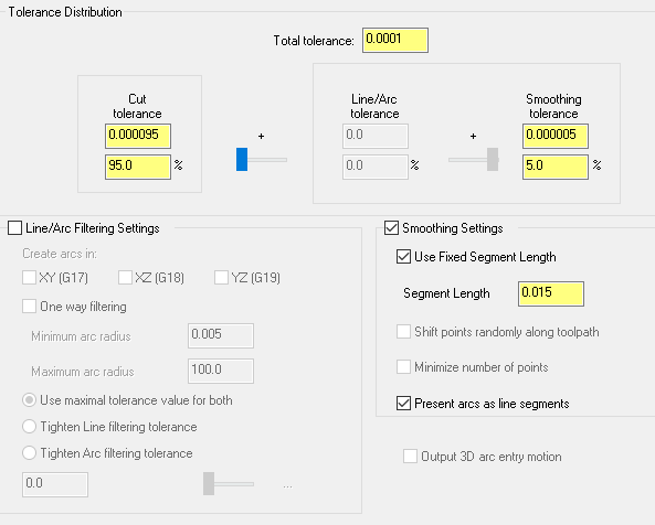
Is there ever a situation to set the total tolerance to .0001? See above png for our current settings... Problem is setting this to .0001 takes a long time to generate with the equal scallop toolpath in mastercam. If we set this tolerance to .001, will it effectively achieve the same results? This is my guess