Search the Community
Showing results for tags 'Macro'.
Found 21 results
-
I am new to using Cimco and have run into an issue trying to set up a Macro. I created some logic in my NC code to check if the vacuum valve is on or off using some IF/THEN/ELSE logic. We have DMS machines with Fagor 8065 controls. These machines use $ to define the logic operator (example $IF). In Cimco it seems the $ character is used to define a user input and will not allow me to create this macro for insertion into my parts programs. I get a Missing question symbol (?) after condition error. Is there a setting to change this character or a work around to get Cimco to accept the macro as is? (CHECK IF VACUUM IS ON) $IF P10==2 $GOTO N1 $ENDIF $IF [V.PLC.O_VAC1==0] #ERROR ["!VACUUM 1 OFF!"] $ENDIF $GOTO N2 N1 $IF [V.PLC.O_VAC2==0] #ERROR ["!VACUUM 2 OFF!"] $ENDIF ;
-
 I'm looking for an automated way to do the following: initial conditions; Mastercam open with parasolid imported 1. create new level 2. Create faces from solid on this new level 3. hide solid from its level I make fully dimensioned drawings in Solidworks and to ensure each model feature from the part is dimensioned, I use Mastercam to change the color of each surface as I dimension it. It has worked very well, but I would like to automate the creation of the faces.
 -
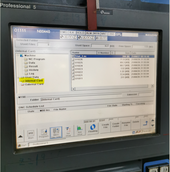
Hi, I am new to this field and need to record cutting time from Makino V33 and V56 (Professional 5 Controller) using dprnt. Currently I am working on following macro to send text to machine internal card (attachment), which is configured as FTP server to receive gcode files from PC. My plan is that since 'Internal Card' folder is shared, my PC will be able to retreat dprnt result from machines if I could get the machine to write text or variable value to this folder as .txt file. Can I please have your advice on following questions: 1) Any way I can determine whether 'Internal Card' folder is a dataserver or flash card storage? 2) May I know the steps/code to dprnt variable value to 'Internal Card' folder? Do I need to have additional command like 'G10L52' & 'N20R4' to change channel no to 'Internal Card' folder? If yes, what channel number is required in this case. 3) As I know 'User Macro Action' has to be turned on for dprnt command to work. May I know how to turn on this parameter in my machines? Apart from Makino with Pro 5 controller, I looking for way to have same proposal to work for other machines with controllers like Fanuc 18i-M, 18i-Mb, Mori Seiki MSX-701 and Heidenhain etc. Any advice is appreciated Thank you. POPEN DPRNT[*************************] DPRNT[Testing*Program*Started] DPRNT[Testing*Program*Ended] DPRNT[*************************] PCLOS
-

Peck drilling with right angle head
MIL-TFP-41 posted a topic in Machining, Tools, Cutting & Probing
Fanuc 31i control... Got an application where I need to peck drill with a right angle head, So the drill cycle will run in the Y axis rather than the Z axis. I started looking into a macro for doing this, but then got to wondering if I am just over complicating things So in my head I was thinking I could call up G18, then a drill cycle...so something like this: G18 G83 G98 Y-1. R.05 Q.1 F100. Is it that easy? Or would I have to do something like a G68 Coordinate Rotation while in the G18 plane? Or just stay with the original macro idea? And if thats the case, anyone got a Y axis peck drilling macro handy? Thoughts? -
 Hello everyone, I'm new to okuma programming and so far only know Heidenhain. (measuring was standard here and much easier) Is it possible to write a macro on my horizontal machine that measures / calculates the angle between two points in x and then rotates this value in the program so that I have "aligned" the workpiece? Okuma MA 600 hii with renishaw. maybe someone has such a macro? Many thanks in advance Regards Philipp
 -
I recently designed a macro program to do face grooves in parts that require a circular finish. I have not yet been able to test it and will keep updating the code here. However, if anybody else ever has a need for it. Here it is. If you do try this code, do so with extreme caution. This program could be incredibly dangerous if operated incorrectly, (think broken part, spindle, tool, etc.) If you do use it, let me know how it goes here. Cheers, Caleb ; PROGRAM DESIGNED TO CUT CIRCULAR FINISH GROOVES THAT ARE NOT ABOUT A ROTATION AXIS ON A PART ; WORK OFFSET SHOULD BE SET TO CENTER AND TOP OF FEATURE DESIRED ; THIS PROGRAM IS VERY DANGEROUS, DO NOT STOP MACHINE DURING CYCLE ; SINGLE BLOCK, FEED HOLD, CYCLE HOLD, FEED OVERRIDE, AND SPINDLE OVERRIDE OVER CAN CAUSE CATASTROPHIC FAILURE ; PROGRAM DESIGNED IN INCH MODE, MAY BE UNSTABLE IN MM ; PROGRAM IS DESIGNED TO CUT FEATURE TO SIZE WITH NO STEPOVER ; ACTUAL SPINDLE POSITION CLOCK POSITION MAY NEED ADJUSTMENT, SEE LINE 60 DEF REAL _F_DIA; FEATURE DIAMETER DEF REAL _Z_DEPTH; DEPTH OF FEATURE DEF REAL _Z_FEED; INFEED OF TOOL, AS LATHE DEF REAL _T_TOOL_OFFSET; B DISTANCE OF TOOL IN SPINDLE, OFFSET OF TOOL FROM CENTER OF SPINDLE DEF REAL _PI; PI CARRIED TO 5TH DECIMAL DEF REAL _H_TRAVEL; ACTUAL DIAMETER TRAVEL, DIAMETER OF FEATURE - RADII OF TOOL*2 DEF REAL _F_RATE; FEEDRATE CALCULATION DEF REAL _LOOP_CUT; CALCULATION FOR LOOP CUTTING DEF REAL _FINAL_Z_CUT; FINAL CUT IN Z DEPTH DEF INT _TOOL; TOOL NUMBER, OR NAME, BEING USED DEF INT _T_HEIGHT; D VALUE BEING USED DEF INT _RPM; RPM OF MILLING SPINDLE ; THESE VARIABLES REQUIRE INPUT BEFORE RUNNING; INPUT OF 0 WILL RESULT IN ALARM ; ***INPUT DATA DESIRED HERE*** _F_DIA=3 _RPM=1 _Z_DEPTH=.050 _Z_FEED=.003 _TOOL=16 _T_HEIGHT=1 STOPRE T=_TOOL D=_T_HEIGHT; TOOL CALL, AND HEIGHT CALL M6 STOPRE _LOOP_CUT=(TRUNC(_Z_DEPTH/_Z_FEED)) _T_TOOL_OFFSET=($P_TOOLL[2]) _PI=(3.14159) STOPRE _H_TRAVEL=(_F_DIA-(_T_TOOL_OFFSET*2)) STOPRE _F_RATE=(_H_TRAVEL*_RPM*_PI) _FINAL_Z_CUT=((_LOOP_CUT*_Z_FEED)-_Z_DEPTH) STOPRE IF _F_RATE>500 GOTOF "MESSAGES_ALARMS_2" IF _F_DIA<=.500 GOTOF "MESSAGES_ALARMS_1" IF _RPM<=0 GOTOF "MESSAGES_ALARMS_1" IF _RPM>=100 GOTOF "MESSAGES_ALARMS_2" IF _Z_DEPTH<=0. GOTOF "MESSAGES_ALARMS_1" IF _Z_FEED<=0. GOTOF "MESSAGES_ALARMS_1" IF _Z_FEED>=.01 GOTOF "MESSAGES_ALARMS_2" STOPRE SUPA G00 G90 Z0.; G17; G54; SPOS=AC(180.); ADJUST POSITION AS NECESSARY, INPUT IS DEGREES G97; X=(_H_TRAVEL*(1/2)) Y0. Z1.; Z.1; G94 G01 Z.005 F25.; G02 X=(_H_TRAVEL*(1/2)) Y0. Z0. I=-(_H_TRAVEL*(1/2)) J0. F=(_F_RATE) S=(_RPM) M3; SPINDLE ACTIVE, DO NOT FEED HOLD!!! CUTTING_ACTION: X=(_H_TRAVEL*(1/2)) Y0. Z=IC(-(_Z_FEED)) I=-(_H_TRAVEL*(1/2)) J0. REPEATB CUTTING_ACTION P=(_LOOP_CUT-1) X=_H_TRAVEL*(1/2) Y0. Z=IC(_FINAL_Z_CUT) I=-_H_TRAVEL*(1/2) J0.; FINAL Z CUT FINAL_DEPTH: X=(_H_TRAVEL*(1/2)) Y0. Z=-(_Z_DEPTH) I=-(_H_TRAVEL*(1/2)) J0.;CLEANUP PASS, REMOVES Z RAMP REPEATB FINAL_DEPTH P=2; 2 SPRING PASSES AT DEPTH X=(_H_TRAVEL*(1/2)) Y0. Z.005 I=-(_H_TRAVEL*(1/2)) J0.; BACK TO CLEARANCE HEIGHT G01 Z.1 F25.; SUPA G00 Z0. M05; M30; MESSAGES_ALARMS_1: STOPRE LOOP MSG ("PARAMETER MISSET, LOW") M00 ENDLOOP MESSAGES_ALARMS_2: STOPRE LOOP MSG ("PARAMETER MISSET, HIGH") M00 ENDLOOP
-
Hi everyone, We just bought Renishaw Productivity Plus for Mastercam X7. I am trying to make it works on our new machine : machine: AWEA 3016 controller: FANUC 31i The dealer modified our post .pst to make it communicate with the Renishaw post ,renmf for FANUC 31i controller. On MasterCam, I am able to post the program. However, when I am trying to run it on the machine, the program tries to open subprogram that doesn't exist on the machine (see the attached file to see all the program that the program is trying to open. Here's the beginning of the program until the error pop on the screen: O0000 (PIECE TEST-6) (AWEA SP3016) (MACHINE GROUP-1) (MCX FILE - G:\RENISHAW PROBING\PIECE TEST.MCX-7) (PROGRAM - PIECE TEST-6.NC) (DATE - DEC-18-2013) (TIME - 11:16 AM) (T60 - RENISHAW OMP60 - H60 - D60 - D0.2362" - R0.1181") (T4 - SLOTTER 1.00 COURT R1/16 PASSE .125 - H4 - D4 - D1.0000" - R0.0620") (T48 - END MILL 3/8 .375 CARB. FINISH - H48 - D48 - D0.3750") #149=0 (RENPROGSTART) #148=0 (RENPROGSTARTEND) (_RENGCODE_START0001) N100 G00 G17 G20 G40 G49 G80 G90 (_RENGCODE_END) (PRODPLUS_BEGIN) POPEN DPRNT[] DPRNT[PROGRAM*START*PGS] DPRNT[**REPORT*VERSION*1F] DPRNT[**PROGRAM*NAME**O] #1=FIX[#3011/10000] #2=#3011-[#1*10000] #3=FIX[#2/100] #4=#2-[#3*100] DPRNT[**DATE*#4[20]**#3[20]*#1[40]] #1=FIX[#3012/10000] #2=#3012-[#1*10000] #3=FIX[#2/100] #4=#2-[#3*100] DPRNT[**TIME*#1[20]**#3[20]**#4[20]] PCLOS M5 G54 G90 at this line FILE NOT FOUND POP G65 P2109 A1. C1. I0. 1181 D2. E2. H60. M0. Q0. R0.T-999U60.V1.W0.91Z1. Right now I called the dealer where we bought the machine, they said that all the program are in the machine... I called the dealer who sold us Productivity plus and they don't know why it doesn't work... I also wrote to Renishaw and I am waiting for a response. I also check every single program in the machine.. Can anyone help me ? Thanks a lot Cedrick Baker Missing Sub Programs AWEA 3016.txt
-
Hello. I am going to explain this the best I can. I manufacture firearms components. Bolts, carriers, gas tubes, gas valves, gas blocks, receivers, hand guards etc. I am looking for a way to identify our parts from others as well as label when they were manufactured. I do not have time to engrave the company name, and date of manufacture though. So I need to develop a system to easily identify both pieces of information. I was thinking about putting a dot with a drill X distance from zero to indicate the month of manufacture. The X dimension would change along with the month. Something like: X= MONTH# 1 (JAN) =.1 2 (FEB) = .15 3 (MAR) = .2 ETC... G81 X#### Z-0.01 R0.1 F10 Would it be something like IF P???? (MONTH PARAMETER) = 1 THEN #### = .1 ? I don't mess with macros much, which is why I'm here. Hopefully this is possible. Thank you in advance.
-
 I wrote this macro to easily find the mid point of X and Y and the Z surface for the picking up of details that are irregular shapes or just difficult to pick up with the Haas Canned Probing Cycles. -It will also will give the overall sizes in the offset page-described in directions. -I added DPRNT if you are using that functionality. -The directions are in the beginning and easy to follow. -There are large spaces in the coding to make it easy to see the questions that will come up on the controller. Hope this helps someone as it helps me all the time. Tom Prebelich (***START OF PROGRAM***) #101= 54 (WORK OFFSET, 54-59) (**MAKE SURE BLOCK DELETE IS OFF FOR FIRST PICKUP**) (PROGRAM WILL PICK UP MID POINT OF X OR Y) (FIRST PICKUP PROBE MOVES + POSITIVE, IN "X" OR "Y") (SECOND PICKUP PROBE MOVES - NEGATIVE, IN "X" OR "Y") (**MAKE SURE BLOCK DELETE IS OFF FOR FIRST PICKUP**) (1-JOG PROBE TO WITHIN .5 OF FIRST SURFACE) (2-CYCLE STAR/RUN PROGRAM) (**NOTE, BLOCK DELETE IS TURNED ON AT THIS POINT**) (3-SELECT JOG) (4-JOG PROBE TO WITHIN .5 OF OPPOSITE SECOND SURFACE) (5-SELECT MEMORY) (6-CYCLE STAR/RUN PROGRAM) (7-PROGRAM WILL ASK IF YOU WANT TO PICK UP Z) (8-SELECT N AND PROGRAM WILL END) (IF YOU WANT TO PICK UP Z CONTINUE WITH THESE STEPS) (--SELECT Y FOR YES AND HIT CYCLE START-PROGRAM WILL END) (--SELECT JOG) (--JOG PROBE TO WITHIN .5 OF THE Z SURFACE) (--SELECT MEMORY THEN CYCLE START) (--PROGRAM ASKS IF YOU ARE PICKING UP Z-THIS IS FOR SAFETY) (--PRESS Y FOR AND MACHINE WILL PICK UP Z) (MID POINT OF BOTH PICKUPS = OFFSET SELECTED) (INDIVIDUAL SURFACE PICKUPS ARE STORED IN G154P01 & G154P02) (OVERALL DISTANCE BETWEEN THE PICKUPS/WIDTH OF BLOCK ARE IN G154P03) (FIRST X PICKUP=G154P01) (SECOND X PICKUP-G154P02) (OVERALL DISTANCE BETWEEN X PICKUP-G154P03) (FIRST Y PICKUP=G154P01) (SECOND Y PICKUP-G154P02) (OVERALL DISTANCE BETWEEN Y PICKUP-G154P03) (-----REMINDERS-----) (YOU WILL BE ASKED TO PICK UP Z AT THE END) (ANSWER WITH Y=YES OR N=NO) (IF NO, PROGRAM ENDS) (IF YES, YOU WILL HAVE TO HIT CYCLE START TO CONTINUE) (-THIS PROMPTS/PREPARES THE MACHINE FOR PICKING UP Z) (JOG PROBE TO .5 OR LESS ABOVE Z PICKUP SURFACE) (HIT MEMORY AND CYCLE START WHICH WILL PICK UP Z) IF[#10503EQ123.45] GOTO 230 IF [#101 LT 54] #3000=20 (WORK OFFSET MUST BE 54-59) IF [#101 GT 59] #3000=21 (WORK OFFSET MUST BE 54-59) /N1 #10501=0 /N5 M109 P10501(USER INPUT FOR AXIS TO PICKUP) (WHICH AXIS ARE YOU PICKING UP?) (HIT "X" OR "Y" ON KEYBOARD) /IF[#10501EQ0.]GOTO5 IF[#10501EQ88.]GOTO100 (GOTO "X" PICKUP) IF[#10501EQ89.]GOTO200 (GOTO "Y" PICKUP) /GOTO1 (BEGINING OF X PICKUP) N100 /(1ST X PICKUP IN + DIRECTION) /G65 P9995 W154.01 A20. D.5 /#110=#14001 /GOTO 110 (2ND X PICKUP IN DIRECTION) G65 P9995 W154.02 A20. D-.5 #111=#14021 (AVERAGE FOR BOTH PICKUPS IN X) #115=[[#110+#111]/2] #7041=#7021-#7001 (SETTING WORK OFFSET FOR X) IF[#101EQ54] #5221=#115 IF[#101EQ55] #5241=#115 IF[#101EQ56] #5261=#115 IF[#101EQ57] #5281=#115 IF[#101EQ58] #5301=#115 IF[#101EQ59] #5321=#115 GOTO 120 N110 #3032=1(TURN BLOCK DEL ON) M30 N120 #3032=0(TURN BLOCK DEL OFF) #10188=#14041 DPRNT[] DPRNT[] DPRNT[FIXTURE*OFFSET*#101[40]] DPRNT[X*WIDTH*#14041[24]] GOTO 220 (END OF X PICKUP) (BEGINING OF Y PICKUP) N200 /(1ST Y PICKUP IN + DIRECTION) /G65 P9995 W154.01 A20. E.5 /#112=#14002 /GOTO 210 (2ND Y PICKUP IN -DIRECTION) G65 P9995 W154.02 A20. E-.5 #113=#14022 (AVERAGE FOR BOTH PICKUPS IN Y) #115=[[#112+#113]/2] #7042=#7022-#7002 (SETTING WORK OFFSET FOR Y) #10188=#14042 IF[#101EQ54] #5222=#115 IF[#101EQ55] #5242=#115 IF[#101EQ56] #5262=#115 IF[#101EQ57] #5282=#115 IF[#101EQ58] #5302=#115 IF[#101EQ59] #5322=#115 DPRNT[] DPRNT[] DPRNT[FIXTURE*OFFSET*#101[40]] DPRNT[Y*WIDTH*#14042[24]] GOTO 220 N210 #3032=1(TURN BLOCK DEL ON) M30 N220 #3032=0(TURN BLOCK DEL OFF) (Y=YES/N=NO, ARE YOU PICKING UP Z) #10502=0 N222 M109 P10502(USER INPUT FOR AXIS TO PICKUP) (ARE YOU PICKING UP "Z"?) ("Y"=YES, "N"=NO) IF[#10502EQ0.]GOTO222 IF[#10502NE89.] XOR IF[#10502NE78.] GOTO 222 IF[#10502EQ89.]GOTO225 (GOTO "Z" PICKUP) IF[#10502EQ78.]GOTO245 (GOTO END OF PROGRAM) N225 #10503=123.45 #3006=1 (AFTER HITTING START JOG Z TO POSITION AND HIT START) GOTO 250 N230 #10504=0 G103P1 N235 M109 P10504(PICKING UP "Z"?) (ARE YOU PICKING UP "Z"?) ("Y"=YES,"N"=NO) IF[#10504EQ0.]GOTO235 IF[#10504NE89.] XOR IF[#10504NE78.] GOTO235 IF[#10504EQ89.]GOTO240 (GOTO "Z" PICKUP) IF[#10504EQ78.]GOTO245 (GOTO END OF PROGRAM) N240 G65 P9995 W#101 A20. H-.5 (SINGLE SURFACE Z) G103P1 N245 #10503=0 N250 M30 (END OF Y PICKUP) (***END OF PROGRAM***)
 -
 Hey Everyone, I was playing around with breaking in a new Haas VF-4SS, and made just a few modifications to the Spindle Warm-Up Program. To be clear, this isn't a "spindle break-in program"; it is used to "fully warm-up the machine", after it has been sitting for a while. This program should take anywhere from 10-30 minutes to run, depending on how you have the setup configured. I added a few features that I thought would be useful to 80% of users, out-of-the-box. Feel free to use, modify, or distribute this Macro; but use it at your own risk! Selway Machine Tool Company is not responsible for any damage that should occur as a result of you using this Macro. This Macro causes Machine Motion, which is the whole purpose of it, but that cause a collision on your machine, if you aren't careful. No Warranty is expressed, or implied, if you choose to use this code. ----------- Ok, legal disclaimer out of the way, what does the Macro do, and How do you use it? What it does This Macro Program is designed to be run in 3 phases: Positions to 'safe start' location, and warms up the spindle by commanding Forward and Reverse alternately, through the RPM range, up to about 6,000 RPM. Then it ramps up to 12,000 RPM, and then "ramps down in reverse" (M04). This is the "initial spindle warm-up". It takes about 3 minutes, 10 seconds to complete. The machine then moves to the "home position" (controlled by variables, and user-defined). This is in "Machine Coordinates", and No Tool-Length-Compensation is used, so be careful! Once at the "home position", we turn on the Spindle at the "start RPM". We then "stroke the machine" in XY, and then in -Z. At the bottom, we increase the spindle speed by the Spindle Increment (default is 500 rpm). The "stroke to the endpoint", is done at "high feed" (variable). The "return stroke" is done in reverse, at the "slow speed". At each point (Start/End), the RPM increases, until we hit the "max RPM". That RPM increment is what breaks the "WHILE/DO/END" Loop. After we have "fast stroked/slow returned", the process is reversed. The machine follows the same "positions and strokes", but goes "slow stroked / fast returned". Each of the "stroke cycles" takes about 6 minutes, on a VF-4SS, with 500 RPM as the "increment", 800 IPM as the "fast feed", and 200 IPM as the "slow feed". So, roughly 18 minutes to do a "full warm-up". But what does this get you? A fully warm, and lubricated spindle. A fully warm, and lubricated set of Linear Axes. At the end of the Macro, the program sets the "S" value to a "safe RPM". (Default 80 RPM) It also sets Spindle Direction to CW (M03), and orients the spindle at the end of the cycle. How do you use it? There are Machine Variables at the top of the Macro, which control the following: Make sure you load a Short and Balanced Tool Holder. Gauge Length should be kept to a minimum. (I used a 2.5" OAL Holder for this test.) #10301 through #10303, control the XYZ Home Position. Typically, all three are 0.0, however, on a machine where there is added travel "above the Z Zero Point", you could have something like #10303=4.0. #10304, #10305, and #10306 control the "XYZ Stroke Position". This is the "endpoint" in Machine Coordinates, of each Axis. WARNING: Make sure you adjust all three of these numbers, if your machine is not a VF-4!!! BE VERY CAREFUL WITH THE -Z STROKE! This Macro does not use Tool Length Compensation. We are driving the "gauge point" of the spindle, not the Tool Tip. At the end of the cycle, there is a "Park Position". This is #10324, #10325, and #10326. This is the final place where the machine stops after warming up. It is possible to change either the "XYZ Start" position, or the "XYZ Park Position" to use any of your Work Offsets. BUT BE CAREFUL! For example, consider if we set XY Park to #10324=#5221, and #10325=#5225, but set Z as follows: #10324=#10303. This would put us at G54 XY, but "Machine Zero" for the Z Position. Feel free to experiment and modify this Macro to suit your own needs, but I highly recommend the following: Run the program through in Graphics Mode 1st, before running it on the control. Turn down the Feed and Rapid Overrides, until the machine has cycled through a complete "stroke" of XYZ. The cycle is designed to -Go Home, -Stroke XY, -Stroke Z, -Return Z, -Return XY. Once you have completed a cycle, and you see the WHILE/DO Loop is "incrementing the Spindle Speed", you should be safe to set Rapid and Feed to 100%. Just remember you're still responsible for operating the machine safely. Make sure you check for clearance, and that all "Park, Stroke, Home, Feed, and Spindle values, are set appropriately for your machine. If you only have an 8,100 RPM Spindle: Remove from N222 - to - N233. (cut out of NC Program) Here you go: % O02222 (WARM-UP-SPINDLE-AND-XYZ-AXES) (MACRO DEVELOPED FOR NGC HAAS MACHINES) (BY SELWAY MACHINE TOOL COMPANY) (CREATED BY: COLIN GILCHRIST, SELWAY AE) (CREATED ON: 01/08/2020. 01:28 PM) (***********************************) (WARNING: YOU MUST CHECK FOR MACHINE CLEARANCE) (BEFORE RUNNING THIS PROGRAM) (THE PROGRAM IS DESIGNED TO "STROKE" THE MACHINE) (XY AXES, AND THE Z-AXIS, ON SEPARATE LINES) (VARIABLES ARE USED TO CONTROL EACH AXIS STROKE) (WE RECOMMEND STOPPING ABOUT .400 FROM THE STROKE LIMIT) (THE MACHINE STROKES IN "BOTH DIRECTIONS") (, WITH A COMBINATION OF RAPID AND FEED) (***********************************) (NOTE: FOR CLASSIC HAAS CONTROL:) ( YOU MUST CHANGE VARIABLE NUMBERS) ( #10300 = #500, #10301 = #501, ETC.) (***********************************) N100 (MAIN START BLOCK) (YOU MUST USE NEGATIVE XYZ POSITION VALUES!) (#10301=X-HOME,#10302=Y-HOME,#10303=Z-HOME) #10301=0. #10302=0. #10303=0. (#10304=X-STROKE,#10305=Y-STROKE,#10306=Z-STROKE) #10304=-49.5 #10305=-19.5 #10306=-24. (#10307=SPIND/INC,#10308=SPIND/MAX,#10309=FEED/MAX) #10307=500. #10308=12000. #10309=800. (VARS FOR RETURN) (#10310=SLOW/FEED,#10311=SPIND/START,#10312=SAFE/RPM) (NOTE: PROGRAM SETS FINAL RPM TO #10312 FOR SAFETY) #10310= 200. #10311=#10307 #10312=80. (XYZ PARK POSITIONS AT START OF WARM UP) (NOTE: CHANGE TO #5221-#5226, FOR G54 XYZABC) (#10324=#5221) (#10325=#5222) (#10326=#5223) (NOTE: CHANGE TO #5241-#5246, FOR G55 XYZABC) (#10324=#5241) (#10325=#5242) (#10326=#5243) #10321=-25. (X-START) #10322=-1. (Y-START) #10323=-4. (Z-START) #10324=-25. (X-PARK) #10325=-1. (Y-PARK) #10326=-4. (Z-PARK) (SAFETY LINES) G00 G17 G20 G40 G80 G90 G94 G98 G187 P1 E.04 G00 G90 G53 G49 Z#10303 (1ST - CLEAR Z, CANCEL TLO) G00 G90 G53 X#10301 Y#10302 (GO XY HOME) (PARK THE MACHINE FOR INITIAL/FINAL POSITION) G01 G90 G53 Z#10321 F #10309 (FAST Z START) S#10312 M03 (SAFE SPINDLE AND DIRECTION) G01 G90 G53 X#10321 Y#10322 F #10309 (FAST XY START) N200 (QUICK SPINDLE WARM-UP) S222 M03 G04 P8. S333 M03 G04 P8. S345 M03 G04 P8. S444 M03 G04 P8. S555 M03 G04 P8. S678 M03 G04 P8. S777 M03 G04 P8. S888 M03 G04 P8. S999 M03 G04 P8. S1234 M03 G04 P8. S1800 M03 G04 P8. S3600 M03 G04 P8. S4444 M03 G04 P8. S5555 M03 G04 P8. S7777 M03 G04 P8. S8100 M03 G04 P8. N222 S8888 M03 G04 P8. S9999 M03 G04 P8. S10234 M03 G04 P4. S11111 M03 G04 P4. S11789 M03 G04 P4. S12000 M03 G04 P4. M05 G04 P4. S10000 M04 N233 G04 P4. S8000 M04 G04 P4. S6000 M04 G04 P4. S4000 M04 G04 P4. S2000 M04 G04 P4. S1000 M04 G04 P4. S500 M04 G04 P4. M05 G04 P4. S250 M03 G04 P4. M05 N300 (SAFETY LINES) G00 G17 G20 G40 G80 G90 G94 G98 G00 G90 G53 G49 Z#10303 (1ST - CLEAR Z, CANCEL TLO) G00 G90 G53 X#10301 Y#10302 (GO XY HOME) (PARK THE MACHINE FOR INITIAL/FINAL POSITION) G01 G90 G53 Z#10323 F #10309 (FAST Z START) S#10312 M03 (SAFE SPINDLE AND DIRECTION) G01 G90 G53 X#10321 Y#10322 F #10309 (FAST XY START) N400 (STROKE XY, THEN Z) (NEGATIVE STROKE IS FAST) (HOME STROKE IS SLOW) (SET VAR AT START) #10311=#10307 G00 G90 G53 G49 Z#10303 (1ST - CLEAR Z, CANCEL TLO) G00 G90 G53 X#10301 Y#10302 (GO XY HOME) WHILE[#11LT#10308]DO1 S#10311 M03 (START SPINDLE) G01 G90 G53 X#10304 Y#10305 F#10309 (FEED FAST TO XY -STROKE) G01 G90 G53 Z#10306 F#10309 (FEED FAST TO Z -STROKE) #10311=#10311+#10307 (INC SPEED) S#10311 M03 (START SPINDLE) G01 G90 G53 Z#10303 F#10310 (SLOW FEED TO Z HOME) G01 G90 G53 X#10301 Y#10302 F#10310 (SLOW FEED TO XY HOME) #10311=#10311+#10307 (INC SPEED) END1 (WE NOW RUN THE SAME STROKE CYCLE, WITH REVERSED FEEDS) (AND REVERSED SPINDLE DIRECTION) N500 (STROKE XY, THEN Z) (HOME STROKE IS FAST) (NEG STROKE IS SLOW) (SET VAR AT START) #10311=#10307 G00 G90 G53 G49 Z#10303 (1ST - CLEAR Z, CANCEL TLO) G00 G90 G53 X#10301 Y#10302 (GO XY HOME) WHILE[#11LT#10308]DO1 S#10311 M04 (START SPINDLE) G01 G90 G53 X#10304 Y#10305 F#10310 (SLOW FAST TO XY -STROKE) G01 G90 G53 Z#10306 F#10310 (SLOW TO Z -STROKE) #10311=#10311+#10307 (INC SPEED) S#10311 M04 (START SPINDLE) G01 G90 G53 Z#10303 F#10309 (FAST FEED TO Z HOME) G01 G90 G53 X#10301 Y#10302 F#10309 (FAST FEED TO XY HOME) #10311=#10311+#10307 (INC SPEED) END1 N999 (PROGRAM END) G187 P1 E.04 G00 G90 G53 G49 Z#10303 (1ST - CLEAR Z, CANCEL TLO) G00 G90 G53 X#10301 Y#10302 (GO XY HOME) G01 G90 G53 Z#10326 F#10309 (FAST Z PARK) S#10312 M03 (SAFE SPINDLE AND DIRECTION) G01 G90 G53 X#10324 Y#10325 F#10310 M05 (SLOW XY PARK) M19 (ORIENT SPINDLE) G187 M30 %
 -
My transfer from main to sub is complete but I still cannot get the turning tools for the sub set. I have attached the program. The lines of read text which are used on the sub do not seem to be doing anything. The text in blue, the main spindle works along with the transfer. Is it possible the operator set the tools used on the sub incorrectly? Could I need to change a parameter bit or something? I have reached out to Mazak but have not received any word yet. Please let me know what you guys think. Thank you 1903.EIA.rtf
-
I've attached the blueprint of the part to be made and my code to machine the 5 slots in the OD. My goal is to have a program that regardless of the tool diameter, programmed radius or # of passes/DOC can be changed with relative ease. I'd like to make #527 passes where each pass is #528/#527 deep (the actual DOC is [#528/#527]/2 because the Y axis is diametrical). I've never used variables to this extent so I'm hoping y'all will look it over and critique my code. In the program I accounted for the key cutter tool radius when I programmed the tool path, so the R value on the offset screen=0. I'm cutting on the minus(-) side of Y0. Thanks in advance! 208.txt DWG.pdf
-
 I've attached the blueprint of the part to be made and my code to machine the 5 slots in the OD. My goal is to have a program that regardless of the tool diameter, programmed radius or # of passes/DOC can be changed with relative ease. I'd like to make #527 passes where each pass is #528/#527 deep (the actual DOC is [#528/#527]/2 because the Y axis is diametrical). I've never used variables to this extent so I'm hoping y'all will look it over and critique my code. In the program I accounted for the key cutter tool radius when I programmed the tool path, so the R value on the offset screen=0. I'm cutting on the minus(-) side of Y0. Thanks in advance! DWG.pdf 208.txt
 -
Hi, I'm a newbie at using G68, so having some issues. i have a square casting that has a round boss on the bottom, i have to hold the round boss and machine the square. i want to use G68 to make sure I'm machining square but also need to set the G54 in the middle of the square casting not of the round boss. i have written what i thought would work but I'm having issues with where the controller stores the macro angular change. I have tried using a G54 for the datum and G55 for just the angle but they store in the same place and keep over writing. % O0 (SQUARE PILOT) (T25|6MM PROBE|H25) (T6|10 MAPAL|H6) (T10|16. AZSTAR BALL ENDMILL|H10) G21 G00 G17 G40 G49 G80 G90 (PROBE) T25 M06 (move from centre) G00 G90 G54 X-46. Y-46. G43 H25 Z20. Z10. G01 Z5. F1000. G01 Z-20. F1000. (corner probe) G00 G90 G65 P9023 A15. I50. J50. B1. S54. G00 Z50. G91 G28 Z0. G00 G90 G54 X37.5 Y37.5 G43 H25 Z20. G00 Z10. G01 Z5. F1000. (centre probe) G00 G90 G65 P9023 A16. X75. Y75. Z-20. S54. G00 Z50. M05 G91 G28 Z0. M01 G21 G0 G17 G40 G49 G80 G90 (10mm MAPAL VH) T6 M6 G0 G90 G54 X-39.105 Y-45.617 S4800 M3 G43 H6 Z50. T10 M8 (READ G68 R#189) G68 X0 Y0 R#189 Z5. G1 Z-7. F1000. X-40.214 Y-42.636 F1100.
-
I am not sure if this where this post should be. Anyway, I am trying to use macro/variable on my T, D offset and H offset. So, my programs will look like this, and this is without subprograms. #1 = 1 T#1 M6 G.. H#1 .. .. G01 G41 D#1 .. #2 = 2 .. This is so operator will only changes one thing on each Tool instead of going through T, then H and all D of that same Tool. From what I understand is that I can only use variable 1-33. I've tested a program on the machine and it runs. Dry run. My concern is that will it run on every program and won't crash the machine?
-
Hi guys, I'm trying to learn how to use macros in MasterCAM. I read some stuff about it and it seems that Visual Basic scripts have something to do about it. Can someone help me?? Thanks.
-
Having trouble with a macro program I am running, it looks as follows: :O5000 (ZERO) G00 Z[#26+0.6] G00 X.0003 Y0. G00 Z[#26+0.02] G01 Z[#26-#7] F#121 X-.0132 Y-.0024 X-.0256 Y-.0072 X-.0374 Y-.0168 X-.0479 Y-.0288 X-.0574 Y-.0445 X-.065 Y-.0625 X-.0703 Y-.0817 X-.0738 Y-.1034 X-.075 Y-.125 X-.0738 Y-.1466 X-.0703 Y-.1683 X-.065 Y-.1875 X-.0574 Y-.2055 X-.0479 Y-.2212 X-.0374 Y-.2332 X-.0256 Y-.2428 X-.0132 Y-.2476 X.0003 Y-.25 X.0132 Y-.2476 X.0256 Y-.2428 X.0374 Y-.2332 X.0479 Y-.2212 X.0574 Y-.2055 X.065 Y-.1875 X.0703 Y-.1683 X.0738 Y-.1466 X.075 Y-.125 X.0738 Y-.1034 X.0703 Y-.0817 X.065 Y-.0625 X.0574 Y-.0445 X.0479 Y-.0288 X.0374 Y-.0168 X.0256 Y-.0072 X.0132 Y-.0024 X.0003 Y0. G00 Z[#26+0.6] M99 % It is a program for engraving a zero as part of a serial number. Everything goes great until I hit the M99 where it comes up with Alarm # 115 : Illegal Variable Number. Any idea why this is happening. Im running on a Fanuc controller using G65 for the macro call to pull up this program. Thanks for the help, -Adam
-
 Hello, I'm wondering, is it possible to record a VBScript in Mastercam, like you can record macros in Microsoft office? Thanks
 -
I hope someone out there will have a use for this. Someone at work gave me the idea. Check it out. O5656(DIAMOND PIN MACRO) (PIN AT 0 DEGREES IS VERTICAL) (ABSOLUTE MACRO) (UNDER DEVELOPMENT) (FORMAT G65/G66 ABDTMWREFS) (A = #1 - INCLUDED ANGLE OF PIN) (60 DEGREES IS COMMON) (B = #2 - G68 ROTATION FROM 0 DEGREES) (D = #7 - DIAMETER OF PIN) (T = #20 - TOOL DIAMETER) (M = #13 - MATERIAL SIZE) (SQUARE OR ROUND) (W = #23 - WIDTH OF PIN CONTACT) (R = #18 - R PLANE) (E = #8 - END OF EM IN Z) (F = #9 - FEEDRATE) (S = #19 - # OF SPRING PASSES) (*********************************) (LIMIT SPRING PASSES TO 3.) IF[#19GT3.]THEN#19=3. (STORE CURRENT XY POSTION) #100=#5001 #101=#5002 (CALCULATE TANGENT POSITIONS) (BASED ON ARGUMENT -A-) (-X-/-I-) #102=[#23/2.]+[COS[#1/2.]*[#20/2.]] (-Y-/-J-) #123=ASIN[#23/2.]/[#7/2.] #103=[COS[#123]*[#7/2.]]+[sIN[#1/2.]*[#20/2.]] (CALCULATE FIRST POSITION -X-) #105=#102+[TAN[#1/2.]*[#103]] (CALCULATE MATERIAL CLEARANCE) #106=[#13/2.]+[#20/2.]+.1 (STORE EACH LOCATION) #110=#100-#106 #111=#101 #112=#100-#105 #113=#100-#102 #114=#101+#103 #115=#100+#102 #116=#101+#103 #117=#100+#105 #118=#101 #119=#100+#102 #120=#101-#103 #121=#100-#102 #122=#101-#103 (SET SPRING PASS COUNTER) #149=#19 (SET ROTATION) #530=#2 IF[#2GT180.]THEN#530=#2-360. G68R#530 (GOTO 1ST POSTION) G0G90X#110Y#111 Z[#8+.1] G1Z#8F#9 G41X#112 WHILE[#149GE0]DO1 IF[#149LT0]GOTO10 #149=#149-1. G1X#113Y#114 G02X#115Y#116I#102J-[#103] G1X#117Y#118 X#119Y#120 G02X#121Y#122I-[#102]J#103 G1X#112Y#111 END1 N10G1G40G90X#110 G0Z#18 G69 X#100Y#101 M99
-
I have an Okuma LB3000 Lathe with live tooling. Im using Mastercam X7 MU1. Im wondering which post I should start with and are they capable of Macro programming??? The macro part isn't a huge deal but I thought Id throw this question out there instead of trying them one at a time. Any feedback is much appreciated. Thanks!!!