Search the Community
Showing results for tags 'rotary'.
-
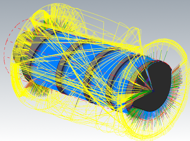
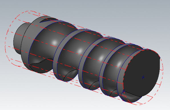
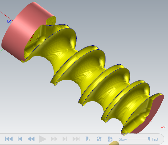
Hello everybody, I am learning mastercam and have an issue with rotary advanced toolpath. I have the workpiece in attachement witch is a variable pitch feed screw. I tried all kinds of toolpaths, swarf milling and morph give good results, but have a little problem witch I couldn't solve : at the first pass, the tool cuts a large amount of material witch will certainly lead to breaking it. On the other Hand, Rotary advanced gives me the passes I wanted : parallel passes with constant depth of cut. Yet one problem still persists, the toolpath actually cuts the workpiece, not only the extra material to cut, so the resulted part is completely wrong. You can see in the generated toolpath that it crosses the workpiece, and in the simulation that it is different from the original workpiece. At the end, I couldn't find the right toolpath for roughing this part without breaking the tool, anyone can help ?
-

Rotary 4th axis, Multi Axis, Toolpath you want?
[email protected] posted a topic in Industrial Forum
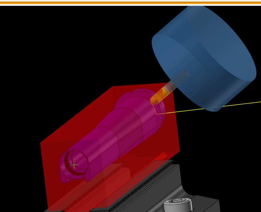
Hi all, I have this part pictured below that I want a nice Multi Axis surfacing toolpath for. At first I started with just 3 axis parallel surfacing tool path but didn't like how it treats the tapered portion near the flats. I could use flow to get something smoother but I am hoping for something like in the picture to where the tool is perpendicular to the surface. I got the result in the picture with rotary axis being set to Y and it makes Arcs over the whole part but has the correct Tool angle. If i set the rotary axis to X it just gives me straight lines and no rotation to keep tool engaged perpendicularly. If anybody has time and is willing to help I have a 6MB zip2go of it I can send you, or if you have a link to a video that would help explain that would be great too. I was trying to find what I want on YouTube but it was taking too much time and seeing as how my toolpath will work It's more of just a learning/preference thing. -
I have created a program that finishes with a 4-axis rotary tool path. I am using a Haas VF2 with the Generic 4-axis haas post from MasterCam. It's about 80K lines of code that get output using G93 Inverse time feed. Feed is non-modal when using G93 so there needs to be an F-value on every single line while G93 is active. About 1 out of every 20 lines does not have an F value and I can't figure out why.. any thoughts as to how I can fix this? Thanks, Al
-
Mastercam Machine Definition - what is it, why do I need it, and how do I use it??? I decided to make this post to help answer the all too frequent questions that pop up related to the Machine Definition, and what role it plays in configuring post processor output. The Machine Definition is a Graphic User Interface that was created by CNC Software to give Mastercam some "intelligence" about the type of machine you are using. There is a distinction that I'm making here between the "Mastercam" interface (where you create Tool Paths) and the Post Processor, that formats your Tool Paths into NC code. When the Machine Definition "format" was created and added to the Mastercam Interface, there was a set of "components" that were developed, along with an "Axis Combination" utility. Together, these form the basic setup to let Mastercam have some "Awareness" of the capabilities of your particular machine. The main issue that confuses the average user is how CNC Software went about "hooking up" certain functions inside Mastercam to work with the Post Processor. If you've had any experience going from 3X, to 4X or 5X, programming a multi-spindle lathe, or even trying to move a program from a Vertical machine to a Horizontal machine, then you've probably been exposed to the Machine Definition issue. In order to understand some of the issues, it helps to get a little historical perspective on how Post Processors are handled. First, Mastercam used to ship with a whole bunch of Post Processors. These posts were "removed" from the Mastercam Installation disks, starting with the Mastercam X series. (or was it X2, I can't remember...) The reason I believe was to help combat piracy, since Mastercam isn't worth that much without a working Post Processor... So you have a situation where Mastercam had a huge "library" of posts, and these were moved to the "Post Installation Program", which is an "exe" file that is available from your Reseller. All of these posts have accompanying Machine Definition Files and Control Definition Files that have to be maintained. This is in addition to the "Generic Fanuc" Post Processors, that are the "template" files for most post processor development projects. Because the Machine Definition was added to Mastercam after Version 9, much of the "Tool Path" functionality and the available post processors, had all been developed without the need or use of a "Machine Definition" or "Control Definition". I've already covered a little bit about Control Definitions, especially how to set the "Default Values", so I won't get into much of the CD. When the Machine Definition Files were added to Mastercam, a decision was made to only "hook up" certain features of the Machine Definition to the Post Processor. This was done (I believe) mainly for practical reasons. It takes a great deal of development time and testing to hook up even one "feature" of the Machine Definition to work with the "template" style posts. 4 Axis vs. 5 Axis One of the biggest differences with how the Machine Definition is handled is the difference between 4X and 5X Post Processors. To understand this difference, it helps to know some info about how the post works internally. With "MP" based Post Processors, there is a huge difference in how Rotary values are calculated. With a 4 Axis Post, the MP.DLL "post engine" makes all of the 4th Axis rotary calculations, based on the orientation of your Tool Plane's Z Axis component. MP will take either the "Top" plane, or the "Front" plane, and use that plane for the "Rotary Zero" plane orientation. When MP "sees" a change in the Tool Plane orientation, it will automatically calculate the new rotary position for you. This happens "behind the scenes", and is based on the value of the Post Variable 'rotaxtyp$'. Since there is a bunch of stuff being calculated "automatically" for you, one of the things that CNC Software was able to do was say "Ok, if you are using a 4X Post, we can make some basic assumptions about your setup." For Mill, this means on a 4X machine you are limited to a machine that is either Vertical or Horizontal. The other limitation is that your Rotation Axis must be Orthogonal, about the X or Y axis. (aligned with +X, -X, +Y, or -Y). For Router, the 4X Rotary is about the Z axis. You cannot use X or Y, only "Z" as the rotation axis for a 4X Router post. For a 4X Machine, (Mill or Router), the Post has logic that reads the "Positive" rotation direction (CW or CCW), and the "type" of axis. (Continuous vs. Index) None of the 4th Axis Posts (Mill, Router, Vertical, or Horizontal) have "Rotary Limits" hooked up inside the post. Only the 5X Post has any concept of "Rotary Limits" built into it. Lathe Mastercam Lathe is the one area of the product that they spent a great deal of time "hooking up", but not in some of the ways you would expect. For a 4X Lathe, Mastercam will handle up too a Dual Turret, Dual Spindle machine, using only the "Generic Fanuc 4X MT_Lathe" Post. On the Machine Definition side, the Post does not read settings from the "components" of the Machine Definition, which is a little confusing at first. What is read is on the "tool path" side, and it is the "Axis Combination" that is read at the "Tool Path" level. That means when you are creating a Lathe path (or Live Tool Milling), you must select the "Axis Combination" to tell Mastercam what set of components (spindle and turret) are being selected. Moreover, you also have to setup the Tool Definition independently (there are turret/spindle settings for top/bottom, and left/right that are not read from the Axis Combination settings.) That said, once you've picked a "Axis Combination", and set the "type" of cut you are doing, there are string settings internal to the post that control the setup and output for all the different turret/spindle combinations. No matter what you mess with inside the Machine Definition, you will not be changing the output in the Post Processor. (A few things like "Max Spindle Speed" for the Lathe Spindles do get picked up and read from the MD, but the NC output is not usually configured this way.) 5 Axis Posts So the Elephant in the Room that I often get asked about is the 5 Axis Post. The Generic Fanuc 5X Mill Post is actually a feat of engineering genius. I say that because "out of the box", it has the capability to support almost any imaginable configuration of 5X machine. The Post is built using "switches" that are numeric variables inside the post processor. These "switches" control the configuration of the NC machine, including the type of machine (Head/Head, Head/Table, Table/Table, or "Nutating" configuration.) Once you specify the "basic machine type", then you configure the Rotary Axis orientation and zero positions, and setup the Rotary Axis Limits. All of these settings are read from inside the Post Processor. The 5X Post has the least amount of features that are "hooked up" to the Machine Definition. "Coolant" is still configured inside the Machine Definition for the Generic Fanuc 5X Mill Post, and some other basic settings like "Linear Rapid Rate". Other than a few parameters though, the bulk of the configuration does not involve the Machine Definition file at all... Part of the issue that is created with the 5X Machine Definition files however is "compatibility" inside Mastercam. There is some logic that actually checks the capabilities of your Axis Combinations, against the existing tool paths you have in your Mastercam file. If a conflict is found, Mastercam will not let you "replace" your MD file. So sometimes it is necessary to add a 3rd Rotary axis to your Axis Combination, to get around that issue. So why even have the MD, if it isn't "hooked up" to everything? The MD is actually a powerful tool, in the hands of a post developer that knows what they are doing. There are many 3rd Party Post Providers like In-House Solutions and Postability, that create their own Posts. These Posts are fully configured to read all the settings "correctly" from the Machine Definition file. I think the main issue is just time and development priorities. Rather than updating the "old stuff", which includes the "MP-based" post processors, it seems that the focus is on the new Mill-Turn product, and the MP.NET language. Another reason is to support "Right Angle Head" or Block Drill attachments. If you have had any exposure to the MP.NET product, you would see that all of the machines being built do use the MD architecture. So, in summary: The MD gives you the architecture to "hook up" component properties to the Post Processor, but most of the functionality is left for you, or your Reseller, to make use of. Axis Combinations are used by the "Tool Paths" themselves. This info is "available" to the Post, but not "hooked up" by default. CNC Software did hook up the 4 Axis Posts, to read some, but not all, of the parameters for the 4th Axis Rotary Settings. For 4X Mills, only Vertical or Horizontal are allowed, and must rotate about X+, X-, Y+, or Y-. The Generic Fanuc 4X MT_Lathe post makes the most use of Axis Combinations, but still relies on the internal variable settings to configure the post. The 4X Router post is the only 4X post that supports a 4X on the Z Axis. (Right Angle Head style). A Programmable 4th Axis, mounted on Z, is not supported in the Mill Posts. The Machine Definition does support Mill Machines using Right Angle Heads, where the offset is done only in XYZ, and the "station" or orientation of the tool is "fixed". So basically, a 3X Mill, using a RAH is supported in the Machine Definition, and by using the "Get angled head" function inside the Tool Path itself. The 5X Post DOES NOT read any Rotary Settings from the MD. This is setup inside the Post itself. Very few settings are read from the MD in the 5X Post. You can "hook this up" yourself, but that requires advanced skills in post editing. You must configure the 5X post, using the variables at the top of the post. Almost all "new" development is being done using the Machine Definition, so at some point this "disconnect" of stuff being "hooked up", or not, will go away. 3rd Party Post Developers, Resellers, and advanced users have the ability to use the MD if they choose to. With MP.NET, it is possible to hook up "Simulation" to the MD, and load in Component Models. This will let you build a machine, and drive it inside Machine Simulation. Well, I hope that helps clear up any confusion or misconceptions about the Machine Definition File inside Mastercam... Best regards, Colin Gilchrist
- 17 replies
-
- 14
-

-
Hi everyone, what are your favorite methods to keep your part rotated toward the operator while doing 5 axis? So far I have been lucky by doing a little re arranging of ops to keep the part visible but I have this part where I am machining the left and right sides and when i post them individually they rotate to the operator but when i post both the second side rotates to the back of the machine. Also curious about which way positive A and B axis rotation should be on your standard 5 axis...on the 5 axis machines here if i rotate to A-90 the rotary platter faces the doors/operator....which is opposite of how our 4th axis rotaries move....Anyway just looking for some good resources.
-
Hello everyone, I'm having trouble configuring the generic fanus 5 axis post. I have a c/b head setup but when I tell the B axis to rotate 90 degrees during a TPlane change, it tilts up much further than 90 degrees. Is there a way to calibrate the postprocessor so that the B axis is in the correct angle? Values for rotary limits seem to only accept units such as millimeters, however 90mm does not correspond to 90 degrees on my machine. Thanks, John.
-
I'm programming a part to mill a diameter with the rotary at 90 degrees and use the rotary to spin the part while cutting. My problem is the code does not out put correctly. It starts at 90 degrees and starts to incrementally go up and then it starts to go down to -270. Below is a section of the code. G0G18G90X-.2062Y0.S1426M3 G56H237Z2.9672 G17Z1.0672 G1Z1.0422F6.33 Z1.0172 Z.9922 Z.9672 C91.528 C93.055 C94.583 C96.111 C97.638 C99.166 C100.694 G42D237C102.218 X-.1793C102.116 X-.1528C101.804 <------------------------Here it starts decreasing the C value. X-.1273C101.29 X-.1031C100.583 This post is from the generic 5 axis post that I converted over for an Okuma mill. When I load up the generic 5 axis machine I get the same result. Not sure if its an issue in the post or my programming. I've attached the mastercam file. Thanks for any help! T.mcam
-
I'm trying to program a drill toolpath for a rotary that has 4 holes at 90 degrees. My problem is that for some reason I cannot select ALL of the four holes using entities option. After I select the four circles it only shows 3 holes being drilled. If I try to add the 4th one it doesnt work. I tried selecting the problem circle first and it will drill the hole. But when I try to select the other three it always wants to skip one. I've attached the file I'm working on. Any ideas? t.mcam
- 3 replies
-
- mastercam 2017
- rotary
-
(and 1 more)
Tagged with:
-
Hello, When I create a program using a 4th axis on a VMC and I'm using many different planes I need to make sure that the work offsets say 1 in the Plane Manager so that I don't get different work offsets for each plane; by default if I do nothing I will get G55, G56 etc. for as many planes as I use. Is there a way that I can force MC to always use G54 regardless of what plane I use with out changing the work offset in the Plane Manager every time I program a part? Thanks for your input. Greg
-
Hello, I have a program that does not follow the entire chain it starts and stops just short of completing the entire chains. I have two chains and the start of one is short and the end of the other is short. The program should start at A+90 and finish at A-90 then moves in the X and then comes back to A+90. The actual cut should starts at A89.523 and cuts to A-90, it starts back at A-90 and finishes at A89.523. I have many parts like this I've done with no issues but this one is giving me problems. I've checked my geometry to see if there was and issue with a surface or chain and I don't see any issues. I also checked the lead in and out I just can't see the problem. TIA, Greg HELP.mcx-9
-
Hey, trying to sort out the final issues with my rotary A axis. I'm using an RT-160 model on a Doosan DNM 500 VMC with a Fanuc i-series controller. The issue I'm having is that the controller stops on the M10 when the axis locks. It reads the M11 perfectly fine and proceeds with the A-axis rotation but when it hits the M10 it locks the axis and does not continue with the program. Has anyone else run into the issue, or have any suggestions as to what the problem might be? Any help is appreciated
-
I downloaded the mpaster X8 post processor. Updated post, control, and machine def to X9. Trying to use the post for a 4 axis HMC (B rotary axis). I make the Top plane the WCS, Front plane is the Tplane --- no B axis index (should be B0.0) when i post. However everything seems to be working fine when I change the Tplane to another plane. In this case I do get B index moves, which is what I want: WCS Top, with Tplane Right outputs B90.0 WCS Top, Tplane Back -- B180 WCS Top, Tplane Left -- B-90.0 Is there a way to get the post to output B0.0 ? thanks Bret
-
Hey Guys, Is it possible to surface the sample attached with a BEM and use 3 or 4 axis. I've tried a few Multiaxis toolpaths "rotary", "curve", "morph between 2 curves" When looking at my sample, the dashed green line extends to the origin so it's basically a can. TIA I have an HA5C rotary for this. Rotary Help Sample.mcx-8
-
Well once again I'm given a job that should be done on our Mazak lathes and am told to get it done. This part is for a gage and it is a sight line. Want me to do it on my 4th axis. Problem is the groove is coming in at an angle. I am told only thing critical is the lines to be in right location where the groove meets the pin dia. Can I get some ideas on how to get there? Thanks for your time. here is a picture until I can remember how to upload a file
-
Hello all professional programmers. I need to nice job and I am trying program surface. I am using 5 axis Haas machine. I move my A axis (along X axis) 30 deg and create plane and toolpath. Now I need repeat my detail 5 times by moving B axis 60 degree each time. I know long way of doing this thing: by creating 5 additional planes. But this way is long and labour intensive.... Is there and easy way of having a control on B axis and duplicate it or rotate another 5 times?? (i dont know maybe by options Right click in operation manager ---- Mill toolpaths ---- Transform ??? Can somebody look into file and try do it ?? In enclosure challenge. Thank You !! What I would like get is : N130 M11 N140 M13 N150 M56 N160 T39 M6 (4.0 VRX BN ER16-100 35MM OUT |T39|D39|H39|DIAM 4.) N170 G0 G54 G90 X5.772 Y-42.491 B0. A30. S10000 M3 N180 M10 N190 M12 N200 G43 H39 Z153.246 N210 Z133.246 N220 G1 Z128.246 F1000. N230 Y-41.922 Z127.928 N240 X5.672 Y-40.702 Z127.252 ......... ....... (toolpath to do surface) G00 B60. (toolpath to do surface) G00 B120. (toolpath to do surface) G00 B180. (toolpath to do surface) G00 B240. (toolpath to do surface) G00 B300. (toolpath to do surface) M30 ROTARY B AXIS INDEXING WITH SURFACES.MCX-6
Join us!
eMastercam - your online source for all things Mastercam.
Together, we are the strongest Mastercam community on the web with over 56,000 members, and our online store offers a wide selection of training materials for all applications and skill levels.


