Search the Community
Showing results for tags 'tool'.
Found 18 results
-
I have made a new tool library with different tool numbers. But since we have many 1000 old programs, they all need to be renumbered. I wanted to write a script that queries me all the tools what new number they have. Since many operations have the cutting data adjusted separately I don't call "op.AssignMillToolBySlot(slot);" but set the number on the tool and still separately on the operation. The whole thing works, except for facing and slot milling. If I call there "op.Commit(false);" the geometry is discarded, also with true the same. Why? Or how does it work differently? Can I also change the tool number without recalculating the operation? That would be much better. Thanks for all ideas Use Mastercam 2023 The actual code is attached Renumberator.csx
-
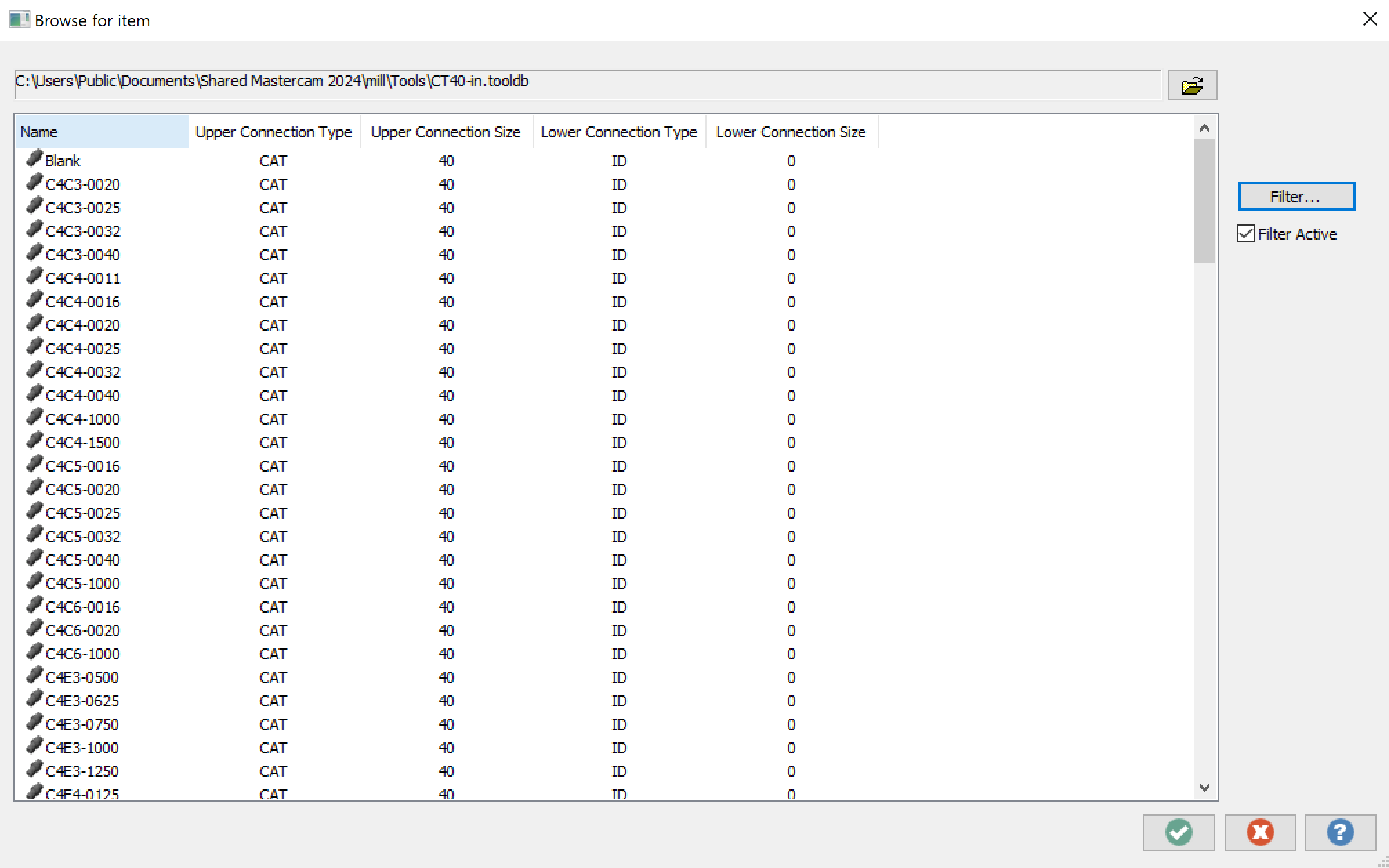
Hello! I was about to start creating a tool library in MasterCAM and wanted to create a tool assembly, first starting by importing some of the defined tool holders that came with my MasterCAM download. However, upon opening the CAT40-in.tooldb file, I get a long list of files labeled with numbers and letters in the form XXXX-XXXX. See attached picture. Even with Google and ChatGPT, I can't figure out what these numbers and letters mean, so I'd figure I'd ask here. Can anyone explain it to me or does anyone have a chart of some sort? I didn't want to have to go through all of them to find the tool holders I purchased. For example, I got a CAT40-ER32-1.85 tool holder from Maritool (https://www.maritool.com/autodesk/477), but Maritool doesn't provide any sort of designation number in the form XXXX-XXXX. Thank you!

-
Is anyone having issues with mcam creating a new tool every time a new type of toolpath is created. Everything is identical about the tools it creates. It is frustrating to say the least. Thanks in advance.
-
Hello everyone. Couple of times I have had this problem in MasterCAM and I can't figure out what is wrong. I created 3D tool, I'm sure that tool is made correct. When I run other part/different toolpath there is no problem. However in this case Mastercam shows me "Tool collision with stock! Continue writing toolpath?" but the thing is that there is only .01'' stock to cut, lead in and lead out is set with clerance. When I allow to write the toolpath and then verify the part, no problem. Verify doesn't show any collision. I tried to switch to 2D tool and everything was good. I'm not getting any information. Can somebody know what is wrong? I add that I had it in the past and I run the program on the machine and was fine. It just bothering me and I would like to know what it's happening. Thanks for help.
-
 In my NetHook I need to compare tools from operations (Mastercam.Database.Tool) with tools from the tool library (CNC.Tool.Interop.TlTool). e.g. I want to compare the name -> OperationTool.Name = TlTool.Name so far good, but if I want to compare the diameter? OperationTool.Diameter = TlTool.? Gaugediameter? Gaugediameter always returns 0 for me and if I want to compare the ToolType? OperationTool.ToolTypeID can be compared, but in TlTool ToolTypeID is only a GUID. So how can I convert a TlTool to a Tool to compare parameters, or what are the comparable parameters? Thanks in advance for any help PS: I use Mastercam 2022
 -
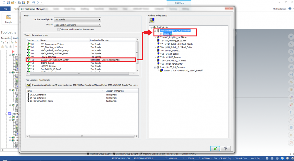
Is it possible to load a tool used in a milling operation onto a tool locator that is loaded onto a tool spindle, It seems I can only load tools used in turning operations onto tool locators. Here I am attempting to load a milling tool onto a tool locator and it doesn't work, I can only load the tool directly onto the tool spindle. Any help would be greatly appreciated!
-
Dear all, Is it possible to calculate the Euler Angles (or the rotation matrix - three (or at least two) vectors defining the tool orientation) from a 5-axis .NCI file? I can reach the tool axis (Z vector) but it is not enough to define the complete matrix, I need at least one more vector. Also, is there some information in the .NCI file that tells me if the machine will privilege the rotary or the linear axis? Thank you in advance. Best regards, Bernardo Freire
-
Hello everyone, I am using 2018 and when I create a face groove tool I would like the add the tools back clearance. Is this possible in 2018 or is it something I will have to wait until 2019 for?
-
Hello to everybody this is my first post so my questions is the next I configured my set-up sheet is working in 90% that I want the only reason that is no ideal is because to the tool list, I cant put automatically in the set-up sheet actually i use 2 ways to do this; put manually in the comments the tool list or create separate the tool list that i want is in the active report the option to attached the tool list simple i tried but for some reason i cant run the active report when i put the tool list in the active report i can upload the file in Rpx if somebody wants look the file
-
Hey friends, I looked around and didn't see a thread that addressed this problem, feel free to direct me if this is a duplicate. I am trying to clean up our lathe post processor and one of the annoying things it does is that sometimes, not always, it duplicates the last tool entry in my tool table. I can't find what controls this process or why some programs have the problem and some don't. My code for the tool table is: ptooltable # Write tool table, scans entire file, null tools are negative tnote = t$ toffnote = tloffno$ tlngnote = tlngno$ spaces$=0 if t$ >= zero, [ "(", *t$, " | ", plistcomm, ")" ] spaces$=sav_spc Which produces the following tool table in my program: (T1 | R .032 OD ROUGH RIGHT) (T2 | R .016 OD FINISH RIGHT) (T5 | OD THREAD RIGHT) (T12 | .118 PART OFF BLADE) (T12 | .118 PART OFF BLADE) Any suggestions on how to stop it from duplicating the last tool? Many Thanks!
-

Version 1.0.0
166 downloads
This sample is in color as it appears in the eBooks version. The print version is grey scale. This step-by-step tutorial teaches you how to create a tool database in Mastercam 2017's Tool Manager. We begin by creating and editing a new cutting tool and holder. From there, we show you how to correctly assemble them and make further edits. Other topics include how to import one tool or an entire Mastercam library into the new database. As well you will learn how to import a .dxf tool file (we use examples from Iscar and Sandvik) and then make any geometry modifications necessary to match Mastercam requirements.Free -
Mastercam 2017 Tool Manager Tutorial SAMPLE (PDF) View File Details coming soon Submitter DanielGingras Submitted 06/07/2017 Category Training Tutorials (Imperial)
-
 This step-by-step tutorial teaches you how to create a tool database in Mastercam 2017's Tool Manager. We begin by creating and editing a new cutting tool and holder. From there, we show you how to correctly assemble them and make further edits. Other topics include how to import one tool or an entire Mastercam library into the new database. As well you will learn how to import a .dxf tool file (we use examples from Iscar and Sandvik) and then make any geometry modifications necessary to match Mastercam requirements.From $35
 -
Version v1.3
This step-by-step tutorial teaches you how to create a tool database in Mastercam X7’s new Tool Manager. We begin by creating and editing a new cutting tool and holder. From there, we show you how to correctly assemble them and make further edits. Other topics include how to import one tool or an entire Mastercam library into the new database. You will also learn how to import a .dxf tool file (we use examples from Iscar and Sandvik) and then make any geometry modifications necessary to match Mastercam requirements.From $20 -
Version 1.0
This step-by-step tutorial teaches you how to create a tool database in Mastercam X9’s Tool Manager. We begin by creating and editing a new cutting tool and holder. From there, we show you how to correctly assemble them and make further edits. Other topics include how to import one tool or an entire Mastercam library into the new database. As well you will learn how to import a .dxf tool file (we use examples from Iscar and Sandvik) and then make any geometry modifications necessary to match Mastercam requirements.From $25 -
I use tons of tool axis control lines to help me surface, and trim molds. I keep having issues whereas the company has a new design that is similar to an existing part. As such I copy the tool path into the new part machine group[using same fixture] . The issue arises when I need to select new Tool Axis Control Lines.... and as soon as I click on the selection button.... Crash to desktop. Originally I thought it was due to me deleting the Tool Axis Control line sketch prior to me deselecting them from the tool path. Though with the parts as stated above, I made a new sketch with a few minor changes. Is there a way for me to dump tool axis control selections? Would deleting the toolpath geometry work? I'm using Solidworks 2017 with Mastercam for Solidworks 2017.
-
 Hi, I am facing a new problem. I have a finishing tool that has 10 degree angle. the sharpest part of the tool diameter is 0.197 inch and the out side diameter is 0.825 inch. the flute is almost 1.78 long. Whenever I want to use this tool the software automatically create the tool path based on the outside diameter even for the really short like 1/4 inch depth cut. I have tried almost all of the tool types but it is the same I guess the software does not recognize the angle. for example, I tried to do a 3 inch pocket with the depth cut of 0.1 inch, the tool path was the same for the whole pocket as i assume it has to get bigger after each depth cut due to the angle of the tool. let me know if you guys know any solution to this. thanks
 -
 Hi all, I made it many-many times... But today... Pfff... I'm try to dump into my favorit buffer the overall length of tool and holder from operations, but no luck... I uncommented the following line, but no luck I can't find pwrttparam$ #Pre-read parameter data "pwrttparam", ~prmcode$, ~sparameter$, e$ Yes, I did this: if prmcode$ = 15832, ToolLength = rpar(sparameter$, 1) #Szerszám teljes hossza if prmcode$ = 15836, ToolHolderLn = rpar(sparameter$, 1) #Szerszámtartó teljes hossza Any idea how can I get the 15832/15836 parameters?