


chriswlbr94
-
Posts
13 -
Joined
-
Last visited
Content Type
Profiles
Forums
Downloads
Store
eMastercam Wiki
Blogs
Gallery
Events
Posts posted by chriswlbr94
-
-
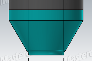
Here is a snip of the portion of the part I'd like to machine with this tool, I also included the tool I created with the chamfer/radius. It has a 30 degree Chamfer and a 1mm radius directly underneath, we would like to just be able to run this tool on the inside of the pocket to created the chamfer/radius in one path. Is this possible? Thanks
-
On 2/28/2023 at 7:04 PM, crazy^millman said:
Without that model and knowing what kind of machine I have no idea if it will work, but he asked so do what he has asked.
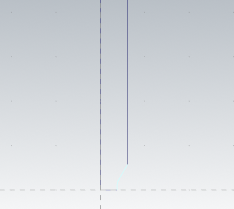
Yes moving to X0 Y0 to make up half of the tool is correct. Like I said close the upper and lower part of the tool. Then when you grab the custom tool just use that level. Make sure that is the only wireframe on that level with no center line or other entities on that level.
Sorry for the delay, I have been busy here at the shop. I created the tool successfully in mastercam, but now when I use it, it says that it is an incorrect tool while creating a toolpath. I've attempted to run this tool on a contour path, but with it being a custom "undefined" tool, it gives me that message. Is there a way to rename the type of tool to be a chamfer tool? Thanks again
-
I was hoping to have a custom made tool with a 30 degree chamfer that was tipped with a 1mm radius. Like a chamfer/radius mixed tool? I was talking over the edge with my manager and he said they used to make custom tools in a similar fashion when he was a machinist. He just told me to draw one up and create it in tool manager, but I'm lost here lol. thank you
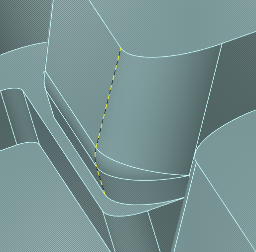
I just took the wireframe of the edge and copied it and set the origin to x0 y0. Is that the incorrect way to do it from a geometry level?
-
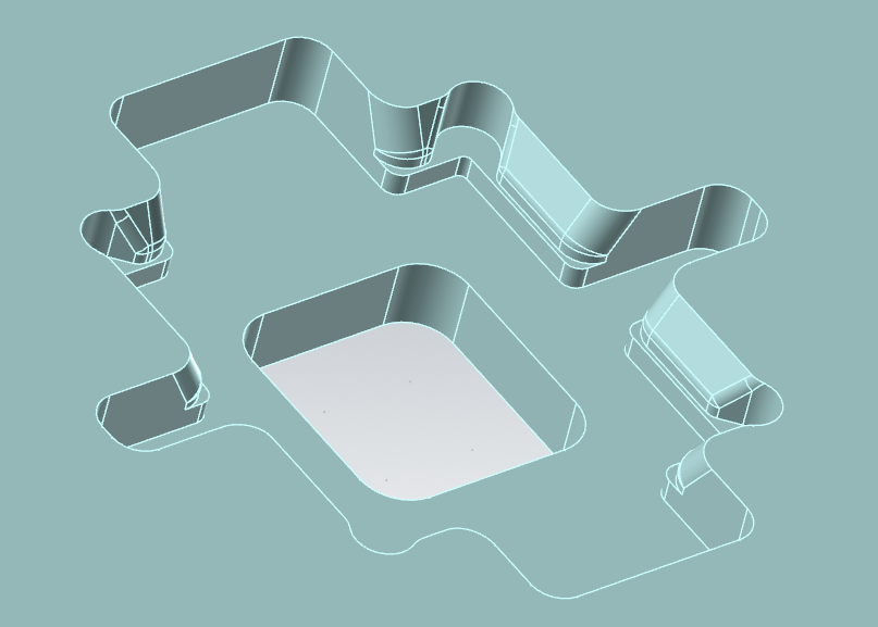
Hey all, I was wondering if anyone would be able to help me understand the process of creating a custom tool from the profile of a portion of a part. The tool will be to create a 30 degree chamfer that smooths into a 1mm radius. I have tried to highlight just the chamfer/radius that I want to mimic the cutting edges, but tool manager keeps giving me errors when I try to import from a level. I'll attach a couple pictures, one of the part (highlighted the chamfer/radius) and one of the profile I have of the tool. Thanks again guys.
-
46 minutes ago, Manofwar said:
That's pretty deep for that size tap. I would switch to peck tapping. Most taps at that size only have 7mm of flute. So the odds are high that the upper portion of the tap is blocking the coolant from doing it's job. As well as the chips from escaping (on the spiral tap.) If you have tapping fluid, use it.
Normally at this size I would use a roll tap to avoid the issue of chip pack, and peck tap to depth. Takes a bit longer, but better then breaking taps constantly.
Thank you for that suggestion, I will give that a go. I just ran the part again and used our tapping fluid instead of the machine coolant, and that worked. Not sure if that was just luck though lol. I'm unfamiliar with a peck tap, in MC i only see the peck drill and tap options.
-
The material is 6061 aluminum, and the depth I'm tapping is only about .32" deep, with a thru-hole drilled prior. I am using a HAAS DM-1 with rigid tapping, and just using the coolant/fluid that we have mixed for our aluminum milling. It is a not a floating tap holder and I have tried using both a spiral flute and straight flute tap. Thanks again guys.
-
Hey all, I had success with the help from you guys last time, so I'm hoping I can get some knowledge on this as well. I am tapping with some M2 x 0.4 taps and they keep breaking
 I can get one hole tapped, and then the next one snaps on me. I have the holes pre drilled thru, and it is the correct dimension hole for this size tap. I'm only running this cycle at 350 RPMs and a feed rate of 5.511 IPM with rigid tapping. I created a new tool in MC with the IPT, diameter, etc. of the tool properties. Any idea why they keep breaking on me? Is it poor chip removal and they keep binding? Thanks
-
Looks like my limit is 9 posts


-
 2
2
-
-
Thanks for all the help guys! I'm a newbie with CNC mills, so I'm sure you guys will hear more from me. Love this forum, no one ridiculed me for such a (seemingly) simple question.
-
HC010BLANK.mcam Hopefully you can see this file, all I want to do is make a program to machine a bunch of these little blanks out prior to doing some actual features on it. We are an R&D company, so we will be making adjustments as needed to any features.
-
The probing cycles that I have attempted to use are the rectangular block, single surface, and outside corner. It probes just fine and outputs work offsets in x,y, and z. I'm using mastercam 2023 and the g54 listed in the program is X-.3948 Y-1.27. Hopefully that helps some with explaining my issue, but I am new to CNC work and am probably not answering that the best. My apologies
-
Hey all,
New CNC machinist here. I have a question on work offsets and how to make it so that my HAAS machine mills out evenly from the stock. I have a program to machine a small rectangle (1.77" x 1.16" x .25") from a piece of stock measuring 2" x 1.5" x .5". I have probed the piece of stock in the machine with the "rectangular block" function numerous times, ""outside corner" and even tried to separately probe each "individual surface" as well. I'm a bit lost on how to accomplish this and have even sides so that I can flip the part and finish it. Anyone on here able to give some advice? TIA.
Custom Tool Creator
in Machining, Tools, Cutting & Probing
Posted
Thank you for clearing that up for me, I was leaning that way originally with the step up path. I just think this tool is make believe and would almost be too good to be true lol. He's an oldschool machinist, so he doesnt really have mastercam experience, just hearsay from people he knows and his past of being a tooling machinist. Our company is supposed to be R&D, so it was a suggestion of how to make manufacturing more efficient and quicker with this tool.