All Activity
- Today
-
Is it possible to use Unified toolpaths independently for 3 axes in the future? Because not all users will use multi-axis licensing...
-
I should understand what you mean...select the geometry and let the software determine that there is no undercut. This is also a way! But it must be suitable for the graphics. If avoidance geometry is used, it may still cause undercut. If there is no multi-axis permission, as Colin said, Flowline and Surface Finish Contour directly support the calculation of undercut, and using avoidance geometry should not affect it. cut straight walls that are in the shadow of overhanging geometry....Surface Finish Contour is more suitable Surface Finish Contour needs to use a tool that can undercut to enable the undercut option. TERRYH did not use the correct tool, so the undercut option is grayed out.
-

Errors when open example c++
eltklas replied to eltklas's topic in Mastercam C-Hook, NET-Hook and VBScript Development
I never used C++, sorry if I ask a lot. I have already added the reference and the windows form. Could you tell me how I show it? my code works in C# //creamos la copia del formulario FrmOffset FrmOF = new FrmOffset(); //hacemos dialog FrmOF.ShowDialog(); Thanks -
We have the 1053 delimit tool path setting on as a recommendation from Camplete. What this does is on 5 axis paths since there is no transition block it zero returns z and starts the next path, no tool change spindle keeps running. It doesn't affect 3plus2 because there is an approach block short that transitions to the next path. I did mess around with the multi axis linking in Camplete but for us it's not worth using.
- Yesterday
-
 Jacob harper joined the community
 -
 berkay joined the community
 -
I can definitely see your point. I will stick to forced tool changes between multiaxis operations on the Matsuuras then For the Haas I have found some "workarounds" that seem to really smooth out the process. Main one being under "feed rate control" in a multiaxis toolpath I will have checked "custom feedrate for clearance blend spline" and "replace rapid with feedrate". and then under the multiaxis link settings I'll have it checked to output feedrates as well. I'll usually have them set around 50-100 inches per minute (with butt puckered and hand on the feed stop button) to first prove it out and if the motion is smooth out at the machine I'll up it to 200-250. Essentially this will force all of the multiaxis toolpaths to stay in TCPC during relinking (while in that operation) but during the actual multiaxis linking moves it does swap back to dynamic work offsets (haas g68.2) so I am still technically rolling the dice a bit. Now really thinking about it I'll probably stop using the multiaxis link on the haas just for standardization's sake though especially since eventually I'll be too busy to prove out every single multiaxis program. Appreciate the insight!
-
That is just crazy I tell you. Crazy talk.
-
Remember getting berated for using the eraser and not rolling the pencil well enough. I still have a drafting table, that thing is heavy!
-

How to do a undercut program
Matthew Hajicek - Singularity replied to TERRYH's topic in Industrial Forum
I just did an undercut fillet with a T-slot cutter the other day. I used Flowline, with Direction and Depth Limits, and it worked perfectly. -
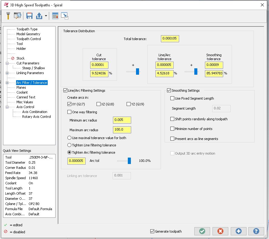
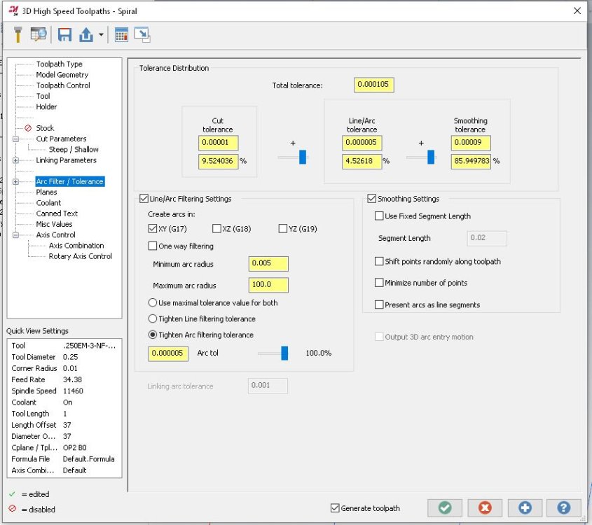
take a look at this file ajmer_ihs_SPIRAL.mcam
-
-
Thanks, I'll give those settings a shot on monday. At least I was on the right track, with the arc filter settings.
-
I typically do not use those 5-Axis linking strategies, or if I do, I use them sparingly. Transition from operation to operation can be tricky. You can get wild unpredictable motion. Much of the motion is dictated by machine parameters (wind/unwind/rotary axis rollover, etc...) In a multi-pallet production environment where unattended operation is the main goal, safe and predictable is your friend.
-
Although my toolmaking apprenticeship, turned into Modelshop/R&D, that quickly turned into the DO at the age of 21. I was REALLY fortunate that my mentor agreed to take me under his wing - he told me "I don't think I can make a silk purse out of a sows ear, but I think I can make a sows ear purse out of you" But we'd hit it off early during my apprenticeship - while work experience in the DO, he gave me my 1st job which was to copy an existing print. Mylar, 5H and 2H pencils, rule ("we don't call them rulers in here as the Queen of England has F'all to do with this job") square, protractor, compass and the most important thing eraser - and away I went. The part was the base of an instrument which was square with the 4x corners turned off, and everything was about the C/L - and I thought I was doing okay when he said "that top right quadrant - tatty - have another go at it"....so the eraser got a hammering and 15 minutes later "that's good, but it shows up the bottom right quadrant - have another go at that"....so out with the eraser again and 15 minutes later rinse and repeat for the left hand side.... End of day I remember him saying "the cleaners will love you tonight - look at all that mess on the floor" But yes, printing was my downfall - CAD was a godsend. There's 2x real arts to being a drafty from a "picture drawing " perspective - neat printing, and the most important one having the initial visibility of first laying the job out in your head so you know you can then get all views and all dimensions on the sheet. As with everything now, things change and it's a lost art - but we now have the other extreme where "everyone can use a computer", so everyone thinks they can be an "engineer"!
-
You guys are great- we are working on all the above. Thank you
-
Did a file get posted somewhere? Am I blind? I'd like to give this a shot as well
-
my drafting teacher made us memorize the factional tables from 0 to 1 by 1/64th We achieved that, then he demanded 1/128th. That knowledge really helped me in my early days as a up and coming machinist. I worked with a guy once who could do that in Mastercam V7 ( no solids) He would design and draft up B/P's for fixtures and tooling that looked like they came out of the Boeing engineering department.
-
Back in high school we had an old German welding/ drafting teacher, much like G-Code describes (drill Sargent/ taskmaster). He would make students cry. I still remember everything he taught us (well I think I remember!!!). Yes drafting with a T-Square and Vellum paper! I had an employee retire after nearly 40 years, he didn't use computers.... he would make "quick sketches" (his description) that were nothing short of works of art. Everything neatly scaled, shaded and sectioned and dimensioned immaculately.
-
I changed the Arc Filter Settings and it seems better (took a while to generate though). Not sure how it will behave on the machine.
-
Being young, I've always thought it would be fun to go back to the time before CAD/CAM, but only for a couple days. I have a feeling I would get sick of it pretty fast.
-
I liked that drafting class and at one point even looked at going to a tech college and making it a career. My dad was a petroleum engineer, working at the bleeding edge of modern tech. This was in 1971/72 and he told me it was a bad idea. He said there was this new tech coming and in 15 years there would be no drafting jobs. He was right too. By the late 80's AutoCad and it's kin had decimated the manual drafting industry. I'd have never made it as a draftsman anyway, My penmanship looks like a drunken chicken scribbling in the barnyard dust.
-
 Ali safi joined the community
 -
You missed the bit then where he said "Listen up G, in 53 years time you'll thank me for this NOW PAY ATTENTION"
-

Errors when open example c++
byte replied to eltklas's topic in Mastercam C-Hook, NET-Hook and VBScript Development
Yes, C++/CLI is the .NET Version of C++ that can be consumed at the c# level You can add a Winform to the C# Project by choosing add new item and choosing a new winform, you need to right click on references and click add reference and select System.Windows.Forms first -
Terry is trying to cut straight walls that are in the shadow of overhanging geometry. You ignore the overhanging geometry and develop a toolpath that cuts the desired straight walls only Then you create avoidance geometry to make the tool tilt and avoid the overhang It is not easy and it's a lot of work but it can be done. You would only go to all this trouble if you did not have a multiaxis license. This doesn't help Terry a bit because he has to build this part on a 3 axis machine.
-
Thinking of going to a 32" curved monitor. Pros Cons
-
This is happening to me, and all I am doing is unshading the solid, and it disappears. I have uninstalled mastercam and reinstalled. Did not fix the issue.