sendithard
-
Posts
30 -
Joined
-
Last visited
Content Type
Profiles
Forums
Downloads
Store
eMastercam Wiki
Blogs
Gallery
Events
Everything posted by sendithard
-
Thank for the help both of you....I will work on this tomorrow and see where I get.
-
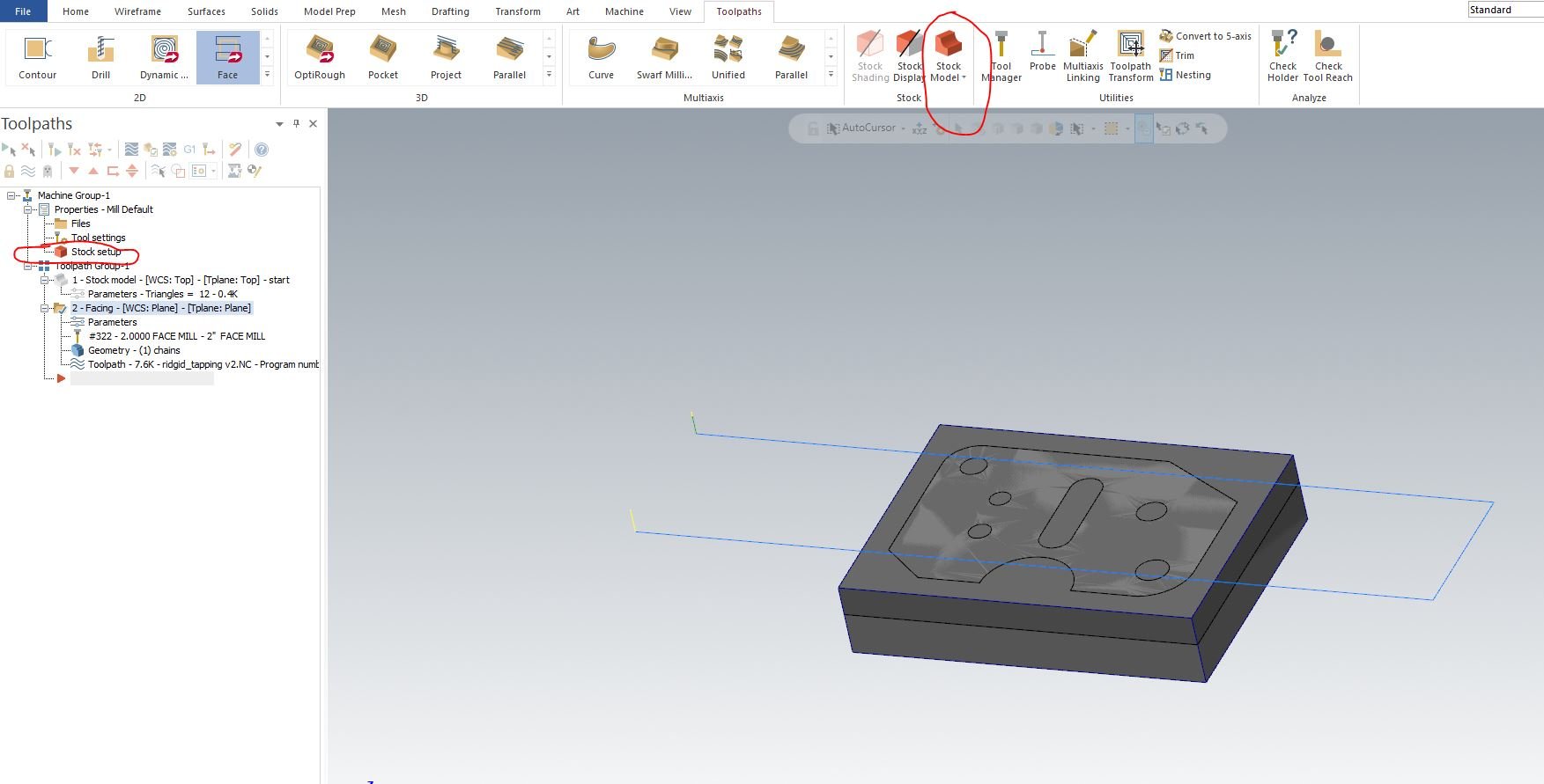
I'm not understanding the lathe stock setup. I've been running into roadblocks for a month and I get frustrated and just quit. HSMworks is much nicer here, I'm not sure why this is so hard for me. When using a mill setup and making stock, I never used the left pane 'Stock Setup' button. I simply create, via wireframe, a bounding box or imported my stock via a step file on a new layer and then in the top horizontal toolbar used 'Stock Model' to define the stock using said new layer. And away you are,,,,I could then do milling features at my pleasure. The only time I would hit the 'Stock Setup' button in the left pane would be to use the backplotting 'simulation' feature. MC seems like it likes to make things challenging by having a backplotting feature and then a more advanced simulation feature. The sim feature must have stock defined in the left pane. Now, doing this with the lathe I get tons or errors, plane not right, bla bla bla. So I look at tutorials and they all BEGIN stock creation by clicking the left pane 'Stock Setup' tab. Why are both so different and what am I not understanding? Below is a quick mill stock setup I never used the 'stock setup' in the left pane.....I only used the horiztonal toolbar 'Stock Model' . Everyone seems to doing the opposite with the lathe. And wtf is the difference b/w the two, I feel like I fit for a rubber room about now.
-
I'm 20 or so practice parts deep into the mill side, so I figured it was time to try my luck with the lathe. I started my Mastercam brain-damage-learning curve career by creating a bounding box solid plus line geometry under its own 'level'(why in the world MC is using adobe illustrator type layers is beyond me). Then I gave up on the brain damage and just started importing my own stock model and using that. I have not played around a lot yet with the lathe, but it does NOT seem to like you importing a stock model or creating a stock model prior to doing the wirefram thingy that everyone seems to be doing. Is there a forced method whereby you must do this wirefram thingy with the lathe and you cannot simple import your own stock model with the lathe? Mill vs lathe stock setup seem drastically different, it is not so in hsm works/fusion. thanks as always.
-
@JParis Gotcha, that makes sense. I'm def not looking at one solution stuff. I'm not sure how MC does scallops strategies yet, but I spent a week on perfecting a scalloping strategy in HSM. It uses scallops very strangely. By nature it collapses a fillet feature toolpath from bottom to top fillet and you finish in the center with both collapsing lines competing for the meetup and you get a poor line in the middle. The workaround is creating a circle much large than the part so that line can't collapse quick enough given your stepover. You can use flow but you get quadruple the points, etc. It makes no sense why hsm/fusion treats the scalloping operation such as this. I saw a fillet tutorial on here recently and it looks real simple.
-
@JParis @Seedy steve I'm somewhat new to cam, fyi. I'm not seeing cutter comp in any of these other strategies or a contour final pass so you aren't arcing into the walls with the dynamic/adaptive paths. Are you all using these none profiling strategies to clean the floors up then just doing a one pass contour to clean the walls? I'll work on the partial chain, I'm not entirely sure how that works since I am looking to profile the entire surface. Thanks.
-
@JParis I got the same toolpath with 2d Dynamic as I did 2d Contour. I don't see an option anywhere to limit the toolpath to a boundary.
-
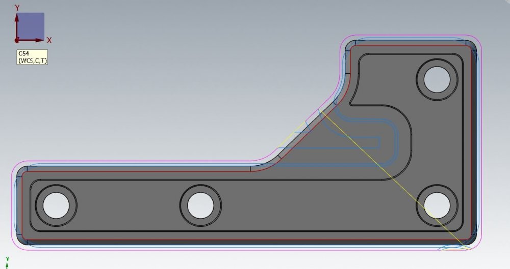
@crazy^millman Thanks, that was a new feature for me to learn, not to mention I had to learn some wireframe stuff. Anyway, I'm not thrilled with what I came up with. Here's why...I began by creating a curve all edges in wireframe boarder(red line below), then did the entity offset(pink outline below) enough to keep my toolpaths I need and eliminate the ones I don't. The problem is this is a hard trim, it even cut my lead in perpendicular moves.
-
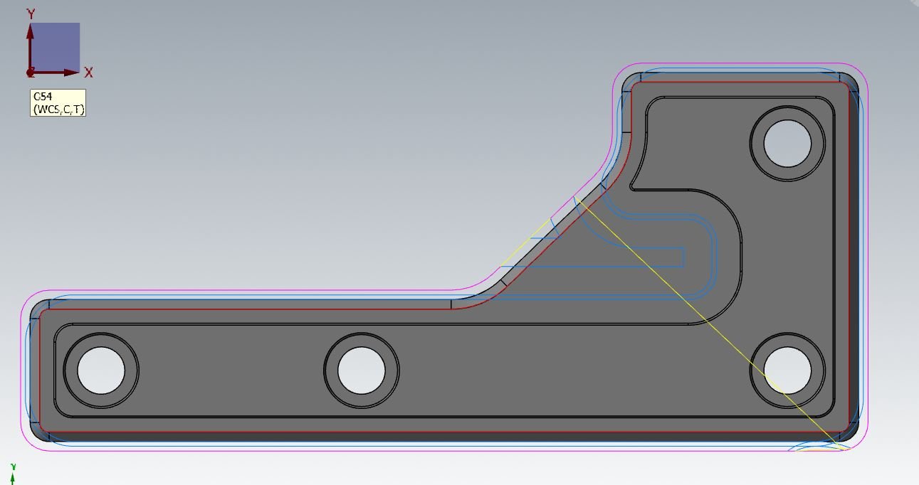
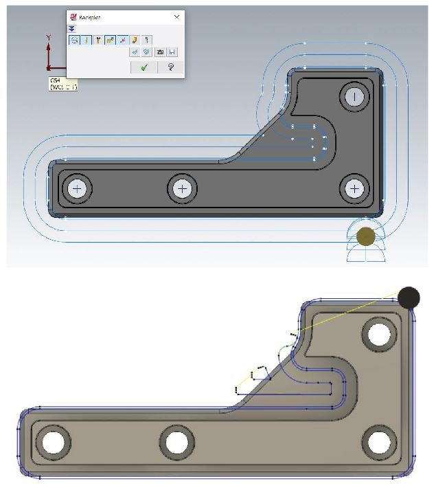
is there a way inside of the contour path to remove the toolpaths from a boundary selection? I see this in roughing, but not contour. Similar to the stock contour selection zone in hsm/fusion. I'm looking to turn the top pic below into the bottom pic. I'm up for a different toolpath idea if you have one as well. Thanks.
-
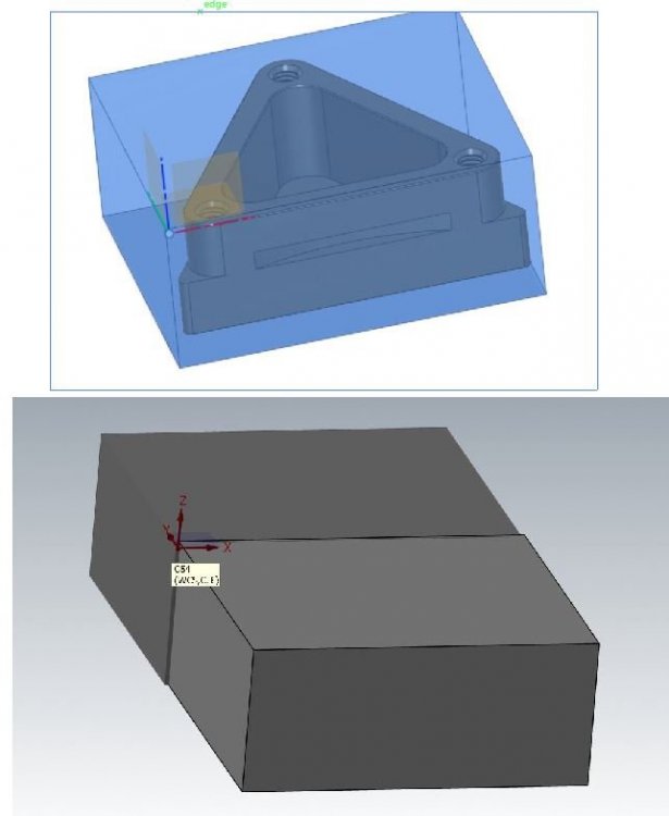
Stock step file relocates to G54 plane
sendithard replied to sendithard's topic in Educational Forum
@Chally72, I'm modeling up the stock and the part together as they sit in the vise, so the stock fully envelops the part. I model both up so G54 will sit flush to the stop part surface. I can therefor, just leave stock model plane unchecked and be done with it. However, I was curious if you can add a plane to the top edge of the stock and make that the stocks master origin. I tried manipulating the stock around for fun and it appeared it was always tied to its native origin. I was never able to tie a new plane down to somewhere on the part and it stick there. It would be nice to create a new 'origin' for the stock so to speak. -
Stock step file relocates to G54 plane
sendithard replied to sendithard's topic in Educational Forum
Thanks for the help, that explains it perfectly for me. -
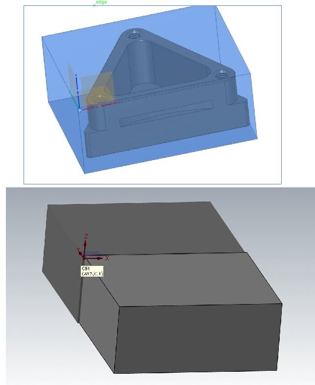
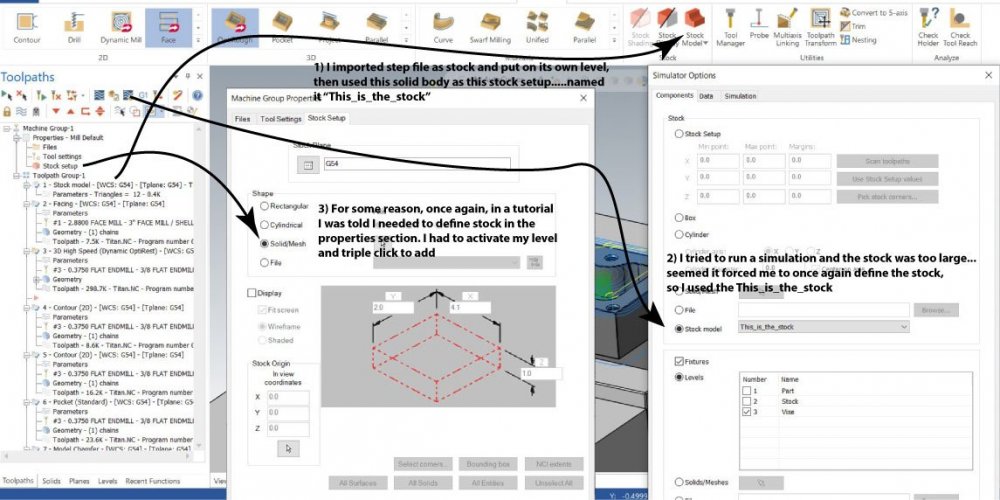
I'm trying to just get thru some tutorials fast now so I'm importing my part and my stock from the same cad file and they are pre-oriented nicely. The only change I want to make is move the G54 from the cad origin. When I merge the stock.step file with the part.step file all is good. The part is perfectly .05 underneath the stock surface, etc. Then I make a G54. Then I click stock model icon and triple click the solid body on the screen and the stock jumps to the new origin so my location is way off. I tried to unclick the stock plane button in the stock model creation deal and the stock stays put, but the stock model in the tree is red checked and once I regenerate it jumps again. Where am I going wrong here? Below shows my part and shaded stock nicely put together. The 2nd pic starts out nice, but once I have to make the stock model it jumps to the new G54.
-
@Colin Gilchrist, I was able to make the changes you stated. I think this looks much better. Agree? Is this a good starting setup for mastercam in the future? Thanks!
-
Colin, Much love for that detailed response. I'll work on that tonight or tomorrow and report back with a toolpath. That's a great post of knowledge I can put in my spreadsheet.
-
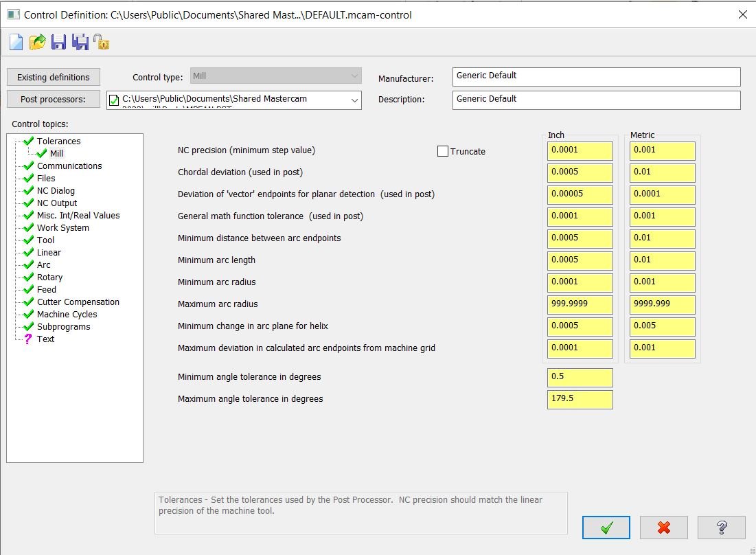
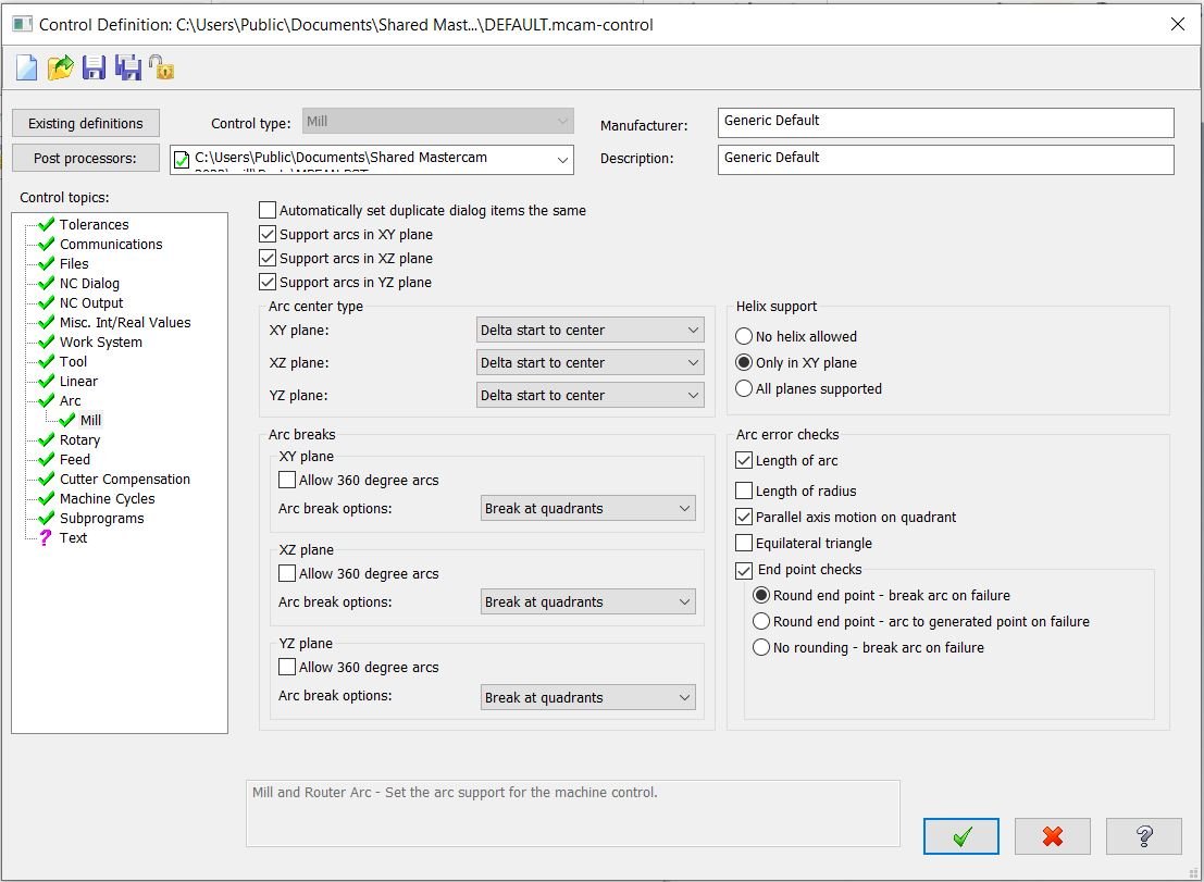
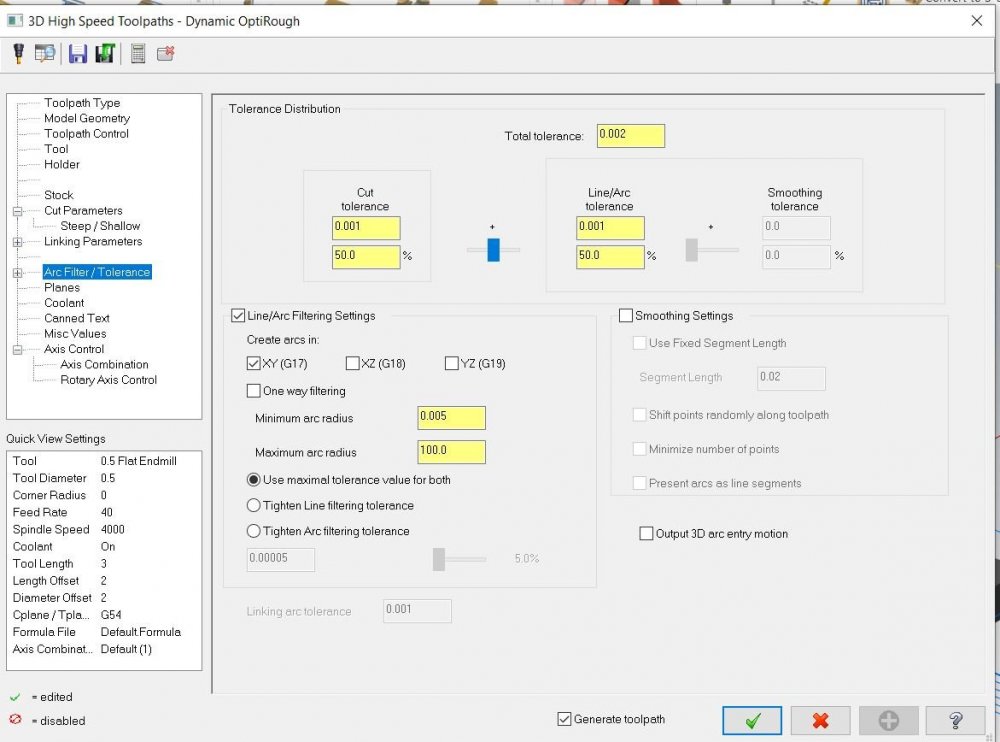
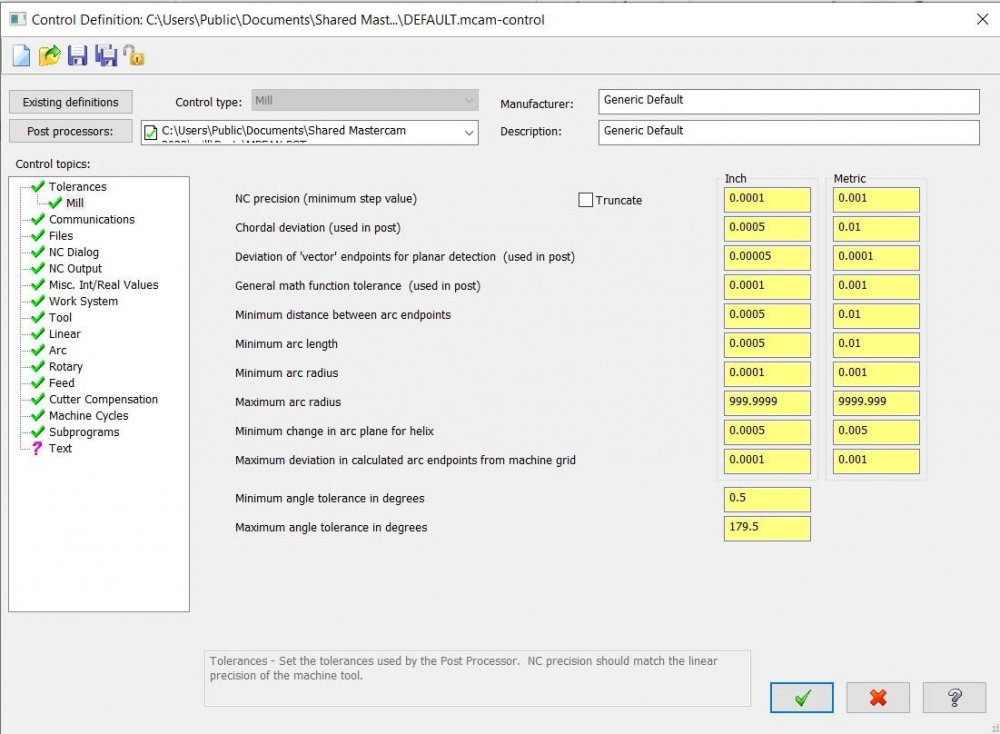
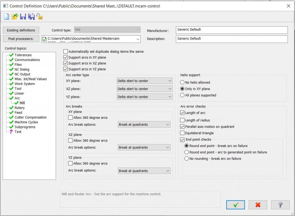
Colin, I wasn't entirely sure what you were discussing here earlier. I see you can go into the machine definitions to change some stuff. The first pic below is the tolerance settings available in the toolpath parameters then the next pics are from the machine definition control area. I'm not sure which settings you were really honing in on. Attached is my finished project to the best of my ability at the moment. Titan_2M v3.emcam
-
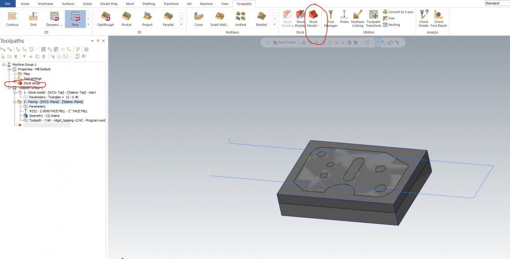
Alight, I played around and it appears you CAN select multiple operations to create a stock.....I failed to see the green checkmarks, I was expecting each op to get highlighted...below are the green check marks I missed. It's these little issues that drive me absolutely crazy learning new software. By the way in that video the gentleman timestamped below has done a facing op, then goes straight into optirough without the ghost cutting issue I had. I'm going to dig around and try to clean mine up, but I'm curious how he got around that: https://youtu.be/aWKRHmsO2PQ?t=1148

-
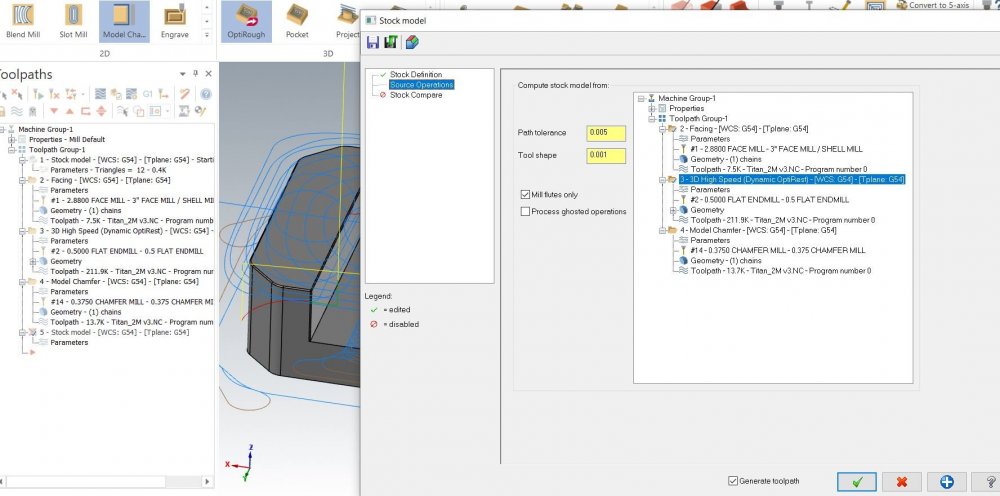
Chally, Very informative, thanks. I watched that video and a lot clicked. I'm decent with fusions cam/hsmworks and to avoid the ghost cutting of material that's already been faced or whatnot you just click rest machining and then select 'from previous operation' and it avoids already cut areas. Here it seems, as you stated, you must create the stock that has been cut. That seemed more work until I saw the power in making stock along the way as you said. Specially for flipping the part. I was going to venture down that road later, I read you can do the old stl route, but this video cleared up the more efficient way. So below you can see I am doing another part and just for fun I'm trying to make a new stock. What has me confused is you can't select multiple operations? So if I wanted to create a new stock before I flip the part, I would need to intelligently make multiple new stocks along the way making sure to pick up on the important cutting operations so when I flip it there won't be extra stock somewhere on the part? I would think you could just click all the operations and the stock would be what it would look like in the verify simulator. Below is the pic where I can't select multiple operations to create a new stock. I can only select one operation. Am I seeing this correct? Thanks.
-
I finished the tutorial project. This go around, I wanted to learn more tools so I imported a vice, stock, part as separate step files and put them on separate levels before doing anything else. Everything seems good. I adjusted what you said earlier to the best of my ability. Attached is the file. I'm baffled why the opti rough is trying to face off above the part. I already did a facing operation to top of part which is G54. I played with rest machining, but to no avail. I'm really confused on why you gotta throw in so many stock models...below is a pic showing my steps on how many times I had to define a stock model. 1st pic below is my current point distribution. Thanks. Titan.emcam
-
Colin, I'm working on finishing this part up today. I've been delaying learning MC and finally broke thru a learning curve and have my arms around it to play on my own. I'll have this program posted later today, thanks for offering to look.
-
Colin, Thanks for the help. That cleaned it up!

-
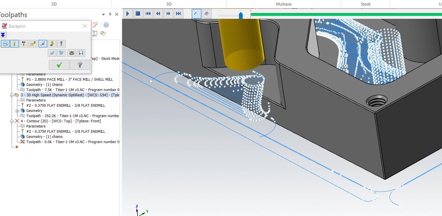
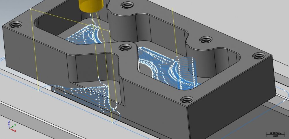
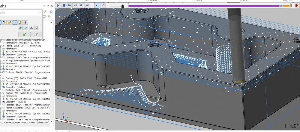
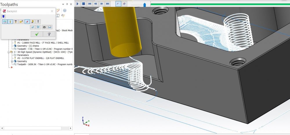
The point distribution on this back plot is showing a lot of points for a straight surface. It is a roughing strategy with wall stock left at .005 and tolerance set to .001. Why would the straight aways contain so many points? Also, if I use verify instead of back plotting I can see the stock getting removed. My issue is if I want to see a wireframe in this setting, wireframe click box doesn't do anything regardless of whether I have stock or model check marked. If I'm looking to see the bull end mill radius matching up with a CAD model fillet should I be using wireframe in back plotting mode instead of verify? Thanks.
-
I have plenty of CAD files, I was curious if anyone in here sometimes drives toolpaths with sketches when advantageous. I don't see a way to pipe in the sketches from a step file of any other means. I'm thinking you need to make the sketched lines/splines/arcs using a level and with MC's tools. If there is a way to import in these lines, arcs, etc. I am interested. Thanks.
-
Is the go to best practice for creating sketches for making tool paths to simply use MC sketch tools? Or is there a way to import these from your CAD program using a step or dxf file? I've only been using fusion cad/cam so it is quite nice to have the integrated ability to show sketches in the cam package. Thanks.
-
vise orientation and bounding box edit
sendithard replied to sendithard's topic in Educational Forum
Thanks for the help. I will look into what you have suggested. I may have a follow up question as I work thru what you said thanks again. -
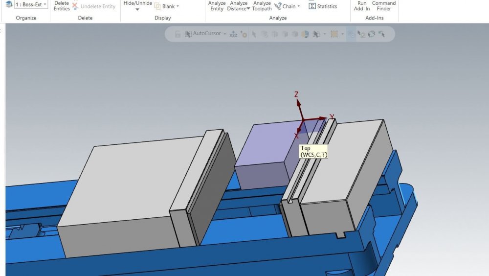
Still a rookie at MC. Ive got three basic questions and appreciate the help. 1) First, when I have my stock aligned to the original gnomon, with z up, I then select merge and import a vise step file. I choose dynamic and place a new gnomon on the back jaw parallel, hopefully centered. I don't see any indication in MC that you are centered. It 'seems' to snap to a center, but I have to go to home and use analyze distance to verify. Then I spin the part and play this movement game until I get close then again it seems to snap to center on the stock bottom center edge. Again, I analyze to verify. Is there a more productive, precise way about this? 2) For those that are doing this from time to time, would it be best to include my stock in my parametric vise file so that when I import my vise in it come with the stock already perfectly set via my CAD program. This seems like the most productive and easiest way to now play movement games inside of MC. 3) I don't understand MC yet b/c there isn't a history tree so to speak. If I wireframe a bounding box as stock, I simply cannot find a way to then edit the bounding box a little larger. For this reason I have been just importing my stock for now. can you edit your bounding box once created and is this how everyone is building stock or are they importing a step file for the stock? Thanks.
-
Thanks for the replies. I have parametric vise setups and some miteebite parametric setups build out nicely in fusion. Is the best workflow to bring in the vise setup with the stock resting tightly inside the jaws as one step file? I feel my workflow would be quite faster to keep these parametric setups in a CAD program I know well. For instance I could quickly enter in a smaller height parallel and longer stock and quickly import that into MC all aligned already, vs moving and placing parallels or stock locations inside MC. Thanks.