tilikoom
-
Posts
13 -
Joined
-
Last visited
Content Type
Profiles
Forums
Downloads
Store
eMastercam Wiki
Blogs
Gallery
Events
Everything posted by tilikoom
-
@crazy^millman Sorry for the delay. The WCS can indeed be updated per the deviations of the FCS. However it requires that 1) the FCS is a known position, 2) all 3 axes must be probed, and 3) the S option is included in the last feature probed. The update occurs on that last feature according to the offset value that was entered. For example: (VERY ROUGH EXAMPLE IN MM) G65 P9814 D15. (MEASURE BORE) G65 P9810 Z F3000. (SOME SAFE Z MOVE) G65 P9810 XY F3000. (SOME SAFE XY MOVE) G65 P9811 Z0. S1. (SINGLE-POINT Z PROBE AND UPDATE G54) In the above snip, XY would be covered in the O9814 bore routine, and Z would be covered in the O9811 single-point routine. The update would occur in G54 after O9811.
-
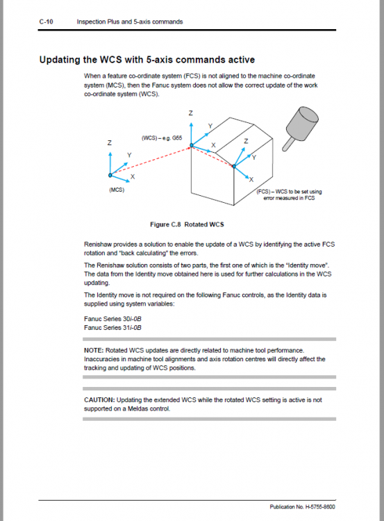
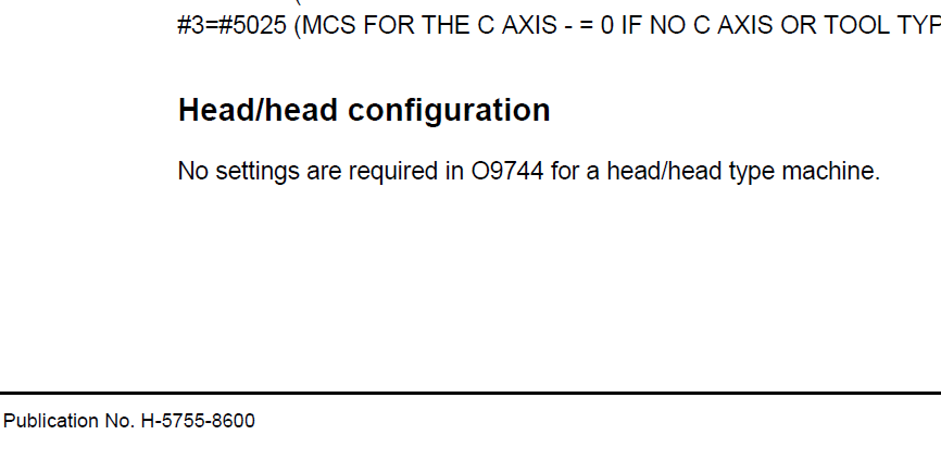
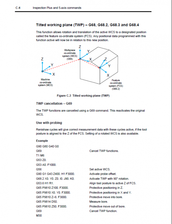
Hello Community, According to the Inspection Plus manual, the WCS can be updated while TWP is active. The updates could be used, for example, to compensate positional errors of the feature coordinate system (FCS). So does this mean that if the WCS was G54, and G68.2 was used to establish a TWP from an angled hole that was at a known location on the part, but the angle hole was out of position by .005 in the Y axis, the .005 error would be added to G54 WCS automatically? According to the Inspection Plus documentation the magic occurs with the settings from macro O9744. Interestingly, for head/head machines, no settings are required for O9744. So on a head/head machine, if the FCS is an angled hole at a known location, and the probe is sent to that location while G68.2 was activated, the measure bore macro O9814 can measure the bore and automatically update the initial WCS G54? Nothing else would have to be done? % O1 (PROBE ANGLE HOLE EXAMPLE) G90 G80 G40 G0 G69 T1 M6 G53 Z0. G53 B0. C0. G59 G90 G1 G43 Z400. G68.2 X0. Y0. Z0. I0. J45. K0. (FEATURE COORDINATE SYSTEM (FCS) - AN ANGLED HOLE AT 45 DEG) G53.1 (POSITION NORMAL TO FCS) G65 P9810 Z100. F3000. G65 P9810 X0. Y0. F3000. G65 P9810 Z−6. F3000. G65 P9814 D15. S6. (MEASURE BORE AND UPDATE WCS?) G65 P9810 Z50. F3000. G69 G53 Z0. M30
-
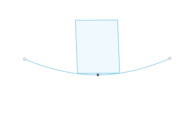
We discovered that just probing the first hole and using it as the machining origin may suffice - sheer luck. So hopefully we will not have to do any complex error compensations. Also got lucky with some other "emergency" jobs that pushed this aside! To answer your question since I was not at liberty to show the real part, this is just a quick mock-up. Unfortunately the real part is mounted to a fixture that would not permit the use of a sine plate.
-
Hello Community, Caught in a bad situation where we were asked to write a manual probing routine to check the alignment of two angled holes on a massively warped fixture that somehow slipped through QC. Currently our CAM software does not support probing. The fixture shown is a mock-up. Confusing matters more is that the fixture has compound angles. It is not the same overall thickness all the way across, although difficult to see in the screenshot. The manager is inexperienced at probing and refuses to make another fixture. He assumes that we can align the part to a machine axis even though it is twisted to all hell. Therefore he insists on writing a manual probing routine that finds the misalignment of the two angled holes as mentioned, and manually adding that discrepancy to a G68.2 plane or G54.4 correction offset in the machining program. Here's a rough draft of our current plan: Create an initial starting point on the bottom corner, and set that as G54 Hard code the exact (or as close as possible) location of the first hole and set that as a G68.2 TWP, then probe the first hole. Move to the next hole in Y+ and probe that hole Document the misalignment of the two holes Add the discrepancy to the G68.2 TWP in the machining program Any feedback would be highly appreciated. Thank you

-
@cncappsjames thanks. If anyone else can share an example of when/why G93 inverse time feed was used, it would be highly appreciated. Thank you
-
Sorry for the lack of clarity. This was driven out of pure curiosity, not by any specific case or machine. It was assumed that there might be some general rules or guidelines for deciding between G93 and G94.
-
Hello eM, For which applications and types of machines is it better to use G93 instead of G94, or inverse time feed instead of feed per minute. Thank you
-
Head/head machine constantly crashed
tilikoom replied to tilikoom's topic in Machining, Tools, Cutting & Probing
Thank you all. I do acknowledge this was largely a rant driven by frustration. This machine has been crashed more times in a year than the total number of crashes I've witnessed throughout my entire career. The floor lead is totally complicit - he just cheats the alignment every time he has a crash and nobody ever knows. He swears the machine is fine. But I beg to differ - it can't be truly aligned to the machine axes after that many crashes. He uses an alignment hack where he determines the amount of run-out in the B and C axes, and enters that amount in the parameters. I believe they are Fanuc parameters 1240, some in the 19600 and 19700 ranges. In this post I should have asked the following questions: 1) What are the appropriate methods of testing, re-aligning, and repairing, a 5-axis gantry machine head that has been crashed an excessive number of times (acknowledging it will never be perfect)? 2) To my understanding the above re-alignment procedure is for fine tuning - NOT for correcting crashes. Is there anyone familiar with this procedure? Am I wrong in this claim? -
We have a head/head 5 axis that gets constantly crashed due to reckless programmers and operators. It has been crashed over 20 times in the last year. The person in charge is remote and is not a machinist, and doesn't understand the situation. The guys who crash the machine know how to do a poor-man's re-alignment on the B and C axes, and they're damn good at it. The machine never gets properly re-aligned by a qualified technician. For example if the B axis is knocked out X degrees, they enter that amount in Fanuc's parameters and the machine runs as if it were aligned. How many cheat-alignments can we get away with before the parts in the head are damaged? Is it normal to cheat the alignment so many times? I haven't worked with too many head/head machines. The truth is these guys are damn good at cheating the alignment, and the untrained eye would never notice it. Just doesn't seem right. We all have an occasional crash, but if this were my company they would be fired for sure. The B and C axes should align without having to manipulate the parameters.
-
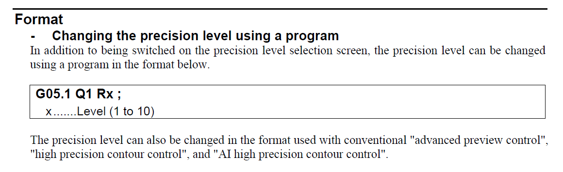
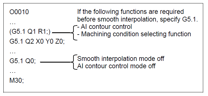
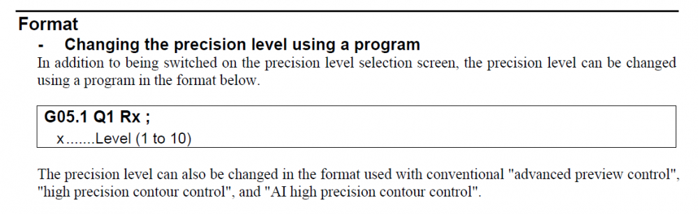
Hello eM, Looking for any feedback on Fanuc's 'AI Contour Control' function. While tasked with cleaning up some of our posts, it was discovered that one of them is generating in the header section this command: G5.1 Q1 R10 The programmers and operators all refer to it as "smoothing", and claim they are using it to control surface finishes, mostly with complex parallel toolpaths. It became a topic of discussion after one programmer complained about having to toggle the R value manually, and asked if we could somehow adjust it in the source file. After some research it is not entirely clear if we are 1) using this command properly, 2) if it should be in the header, and 3) if this is a good way to control surface finishes. Firstly, it doesn't appear that we are using it as a "smoothing" function per the Fanuc manual B-63944EN 310A5 as shown in the first photo. We are using it as a 'Machining Condition Selecting' function as shown in the second photo. Secondly, should this command be permanently baked into the header, or activated within individual toolpaths only when needed? Thirdly, is this a recommended method of controlling surface finishes? Would love to hear about anyone's experiences with this command. Sorry in advance if anything was overlooked. Thank you Format for using it as a 'smoothing' function: Format for using it as a 'machining condition selecting' function: using this command
-
Sharp corners on 3d o-ring groove shape
tilikoom replied to tilikoom's topic in Machining, Tools, Cutting & Probing
I didn't commit to anything - just threw the idea out there. A colleague of mine says that Robb-Jack might be able to make something like this. I don't have experience working with sinkers but I'll look into that too. Unfortunately I do not have the authority to turn him away. Managers here are just as clueless - bad situation. Blind leading the blind. Once again great story! Race track is a good analogy. You bring up some interesting points about 5-axis features. Reminded me of some issues I've had maintaining perpendicularity between the machine head and the part surface on head/head machines. I had to sort of brute-force my way through the process. I've also experienced that same C-axis winding issue. I'll probably make some separate posts about these issues with more detail. -
Sharp corners on 3d o-ring groove shape
tilikoom replied to tilikoom's topic in Machining, Tools, Cutting & Probing
Thank you All - great community. Yeah there's no convincing this engineer. He says there's no allowable radius. I proposed having an end mill made with a very subtle radius as shown below in the hand sketch - still no reply. Any thoughts on this idea would be highly appreciated. The 40ft rail story is classic - insane but not surprising. Thanks for sharing that great story.
-
Hello, Apologies in advance if this is the wrong channel. Looking for some advice on putting an o-ring groove on the top of an unusual 3d shape. An engineer insists on putting sharp corners inside of the groove. Below is a hand sketch of an isometric view of the groove on the top surface. It seems inevitable that a flat end mill would result in the effect shown in the other photo, where the two corners are dragging along the geometry. This is on a 5-axis head/head machine. It seems the only way to achieve this is to rough it with a ball end mill, and finish the corners with a tiny ball end mill. Any thoughts would be highly appreciated.