


amir_cnc
-
Posts
16 -
Joined
-
Last visited
Content Type
Profiles
Forums
Downloads
Store
eMastercam Wiki
Blogs
Gallery
Events
Posts posted by amir_cnc
-
-
Hello
I am working on dmu 50 post
here is the post setup:
#Assign axis address
str_pri_axis : "B"
str_sec_axis : "C"
str_dum_axis : "A"#Toolplane mapped to top angle position strings
str_n_a_axis : "A"
str_n_b_axis : "B"
str_n_c_axis : "C"mtype : 3
head_is_sec : 0
rotaxis1$ = vecz #Zero
rotdir1$ = vecx #Directionrotaxis2$ = vecx #Zero
rotdir2$ = vecy #Direction
p_nut_restore
result = updgbl(rotaxis1$, "vecz") #Zero
result = updgbl(rotdir1$, "vecx") #Direction
result = updgbl(rotaxis2$, "vecx") #Zero
result = updgbl(rotdir2$, "vecy") #Directionsaxisx : 0 #The axis offset direction?
saxisy : 0 #The axis offset direction?
saxisz : 155 #The axis offset direction?r_intersect : 0 #Rotary axis intersect on their center of rotations
n_saxisx : 0 #The axis offset direction?
n_saxisy : 0 #The axis offset direction? 178.763
n_saxisz : 0 #The axis offset direction?n_r_intrsct : 0 #Rotary axis intersection with nutating (normally zero) 0
frc_cinit : 1top_type : 2
shift_90_s : 1
vmc : 1
rot_on_x : 3 #0 = Off, 1 = About X, 2 = About Y, 3 = About Z
rot_ccw_pos : 0
rot_type : 1adj2sec : 1
auto_set_lim : 1
pri_limtyp$ : 0
sec_limtyp$ : 0pri_limlo$ : 0
pri_limhi$ : 360
#Set intermediate angle, in limits, for post to reposition machine
pri_intlo$ : -5
pri_inthi$ : 365#Set the absolute angles for axis travel on secondary
sec_limlo$ : -75
sec_limhi$ : 75
#Set intermediate angle, in limits, for post to reposition machine
sec_intlo$ : -80
sec_inthi$ : 80bias_null : 0
use_tool_plane_as_bias : no$
#Machine base matrix (Base matrix to map positions into)
matb1$ : 1
matb2$ : 0
matb3$ : 0
matb4$ : 0
matb5$ : 1 # 1
matb6$ : 0
matb7$ : 0
matb8$ : 0.707107
matb9$ : -0.707107I get tis error when generating G-codes : "ERROR-SETUP FOR PRIMARY OR SECONDARY AXIS IS ILLEGAL"

-
Good tips
ThanksI'll try in real
-
 1
1
-
-
25 minutes ago, amir_cnc said:
I have a related question:
for example, we have a table-table(C-A) 5axis cnc, and the spinldle is aligned in the Z axis.
In this case, for 2 & 3 axis operations, for output arcs with G2 and G3, on planar surfaces,
Is it necessary to change the top-map value from zero?also in TNC controllers (heidenhain machines) , for arcs, we need to add CYCLE 19 or not?
-
I have a related question:
for example, we have a table-table(C-A) 5axis cnc, and the spinldle is aligned in the Z axis.
In this case, for 2 & 3 axis operations, for output arcs with G2 and G3, on planar surfaces,
Is it necessary to change the top-map value from zero? -
Mastercam have (shift_z_pvt) solution.
It works and fixed.
-
Hello
I need to move all Z coordinate in gcodes, about 100mm downer.
I need this for all 3, 4 and 5 axis moves.
I did try achieve that with (saxisz), but not gain.
How can I do that?
-
Maybe
Thanks
-
yes , but not working
I put here my 5axis setting
---------------------------------------------------------------------
#Assign axis address
top_map :3
str_pri_axis : "C"
str_sec_axis : "A"
str_dum_axis : "B"mtype : 0
head_is_sec : 0
rotaxis1$ =-vecy
rotdir1$ =-vecx
rotaxis2$ = vecz
rotdir2$ = -vecyp_nut_restore #Postblock, restores original axis settings
result = updgbl(rotaxis1$, "-vecy")#Zero
result = updgbl(rotdir1$, "-vecx")#Direction
result = updgbl(rotaxis2$, "vecz")#Zero
result = updgbl(rotdir2$, "-vecy")#Direction
use_tlength : 0
toollength : 0
shift_z_pvt : 0
shft_misc_r : 0
#Offset in head
saxisx : 0 #
saxisy : 0 #
saxisz : -60brk_mv_head : 1
brk_max_ang : 2
top_type : 4
shift_90_s : 1
adj2sec : 1
pri_limlo$ : -99999 #C_axis
pri_limhi$ : 99999pri_intlo$ : -365
pri_inthi$ : 365sec_limlo$ : -45 # A_axis
sec_limhi$ : 45
sec_intlo$ : -45
sec_inthi$ : 45bias_null : 1
spind_align : 3
#Machine base matrix
matb1$ : 1
matb2$ : 0
matb3$ : 0
matb4$ : 0
matb5$ : 1
matb6$ : 0
matb7$ : 0
matb8$ : 0
matb9$ : 1----------------------------------------------------------
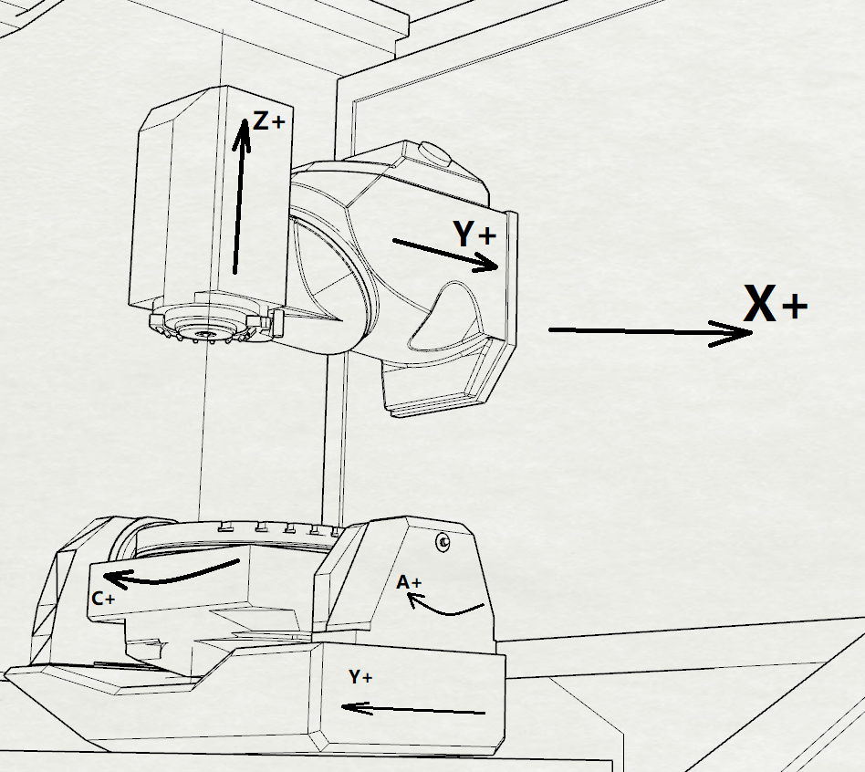
also a my machine axis is attached.
-
3 hours ago, JParis said:
In a post I Have it is set like so...
brk_mv_head : 1 #Break the 5 axis moves to remove gouge
brk_max_ang : -40 #'brk_mv_head' maximum angle move, applied if chordalbut I want break angles in both positive and negative direction
-
Hello
I have a big problem with "brk_max_ang" (breaking all angles)
My machine is a TT 5-axis CA (A axis +45 ~ +30)my post just convert the angles between A+45 to A0 by 5 degrees.
But when it goes from A0 to A-30, it cannot break the angle.the setting is :
brk_mv_head : 1 #Break the 5 axis moves to remove gouge #** 0
brk_max_ang : 2 #'brk_mv_head' maximum angle move, applied if chordal 5
GCODE :
; operation: MJ1
90 L X-2.5 Y+120.108 C+0 A+45 R0 FMAX
100 L Z+286.03 R0 FMAX
110 L Z+188.03 R0 FMAX
120 L Z+186.03 F200
130 L Y+133.77 F1000
140 L Y+126.064 Z+190.075 A+43.216
150 L Y+118.045 Z+193.967 A+41.39
160 L Y+109.723 Z+197.68 A+39.522
170 L Y+101.111 Z+201.188 A+37.617
180 L Y+92.227 Z+204.464 A+35.677
190 L Y+83.091 Z+207.483 A+33.705
200 L Y+73.727 Z+210.222 A+31.707
210 L Y+64.166 Z+212.658 A+29.685
220 L Y+54.437 Z+214.774 A+27.645
230 L Y+44.575 Z+216.552 A+25.593
240 L Y+34.617 Z+217.982 A+23.532
250 L Y+24.601 Z+219.054 A+21.468
260 L Y+14.565 Z+219.764 A+19.407
270 L Y+4.549 Z+220.113 A+17.355
280 L Y-5.408 Z+220.105 A+15.315
290 L Y-15.271 Z+219.748 A+13.293
300 L Y-25.004 Z+219.053 A+11.295
310 L Y-34.576 Z+218.036 A+9.323
320 L Y-43.956 Z+216.715 A+7.383
330 L Y-53.119 Z+215.11 A+5.478
340 L Y-62.042 Z+213.243 A+3.61
350 L Y-70.708 Z+211.137 A+1.784
360 L Y-79.101 Z+208.815 A+0
370 L Y+12.888
380 L Y+76.688
390 L Y-67.803 Z+211.246 A-30
400 L Y-53.803
410 L Z+213.246 R0 FMAX
420 L Z+311.246 R0 FMAX
M5 M9
-
2 hours ago, crazy^millman said:
Tool Length has to be accounted for somewhere. The CAM with the correctly configured post could care less, but for holder avoidance and to use CAM to is true capabilities then taking the time to define all of that there will be the correct process. You never mentioned the control is it a Heidenhain or Siemens?
Hi man
Yes you are right.
My controller is a Heidenhain TNC530.
My operation is shown very well in the car simulation. I builded miy machine in Mastercam MachineSim to check better.Although, I worked with an OSAI PADE 5 Axis Head/Head for several years.
For that machine, I would definitely enter the tool length in the G-code, because of RTCP..
But in table/table Vertical CNC machine, Just face the tool tip on the reference part face, for each tool
Thanks
-
Hi David
I manually place a Mill-Tool with a tool length of 150mm.
And I entered the value of 150mm in HMI-ToolManager.
Also I am enter The "Tool CALL 0" in G-Codes.
But when running the program, only the Z-Axis changes.
If I change the tool length to 0, Just Z axis move down 150mm.
!
But my main question is: on this type of machines(HT , BC), should the tool height be determined by the HMI or Block of "Tool Def", or not?Because in my previous machine, which was a (TT , CA), I did not need to enter the height of the Tool for Single-Tool machining. And I just entered the "Tool Call 0" without tool length, And did working fine.
-
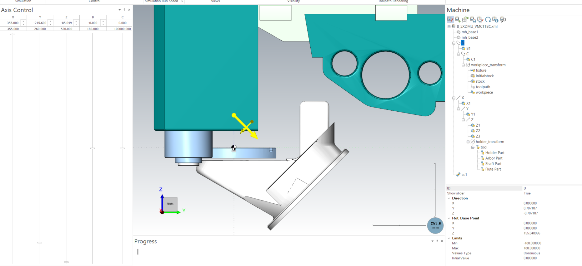
Hello
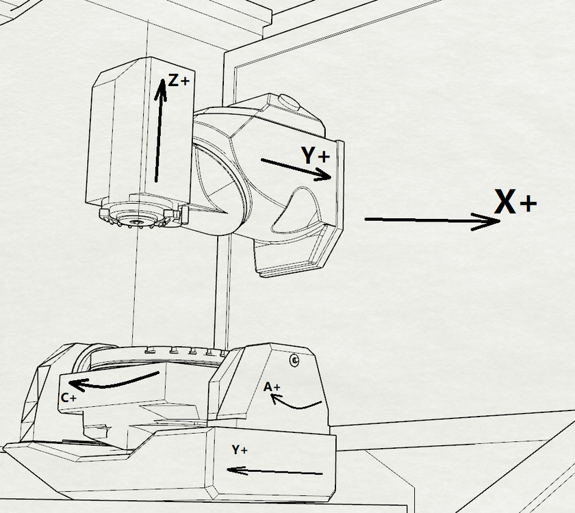
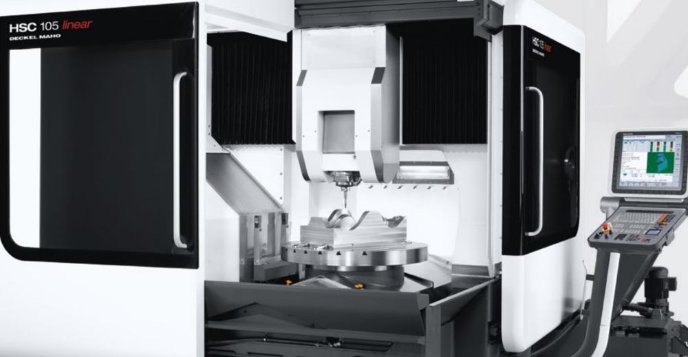
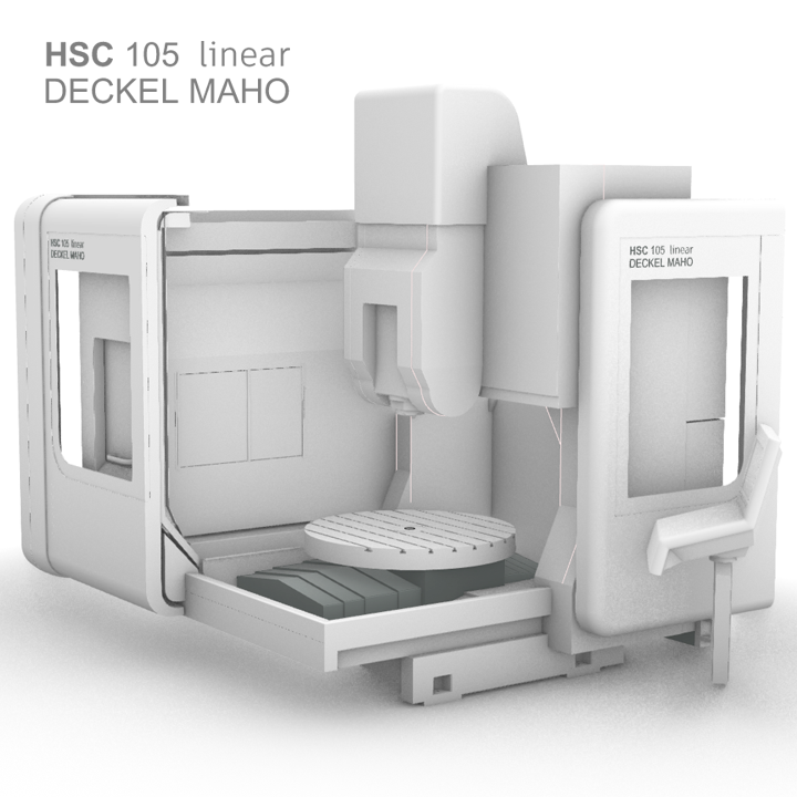
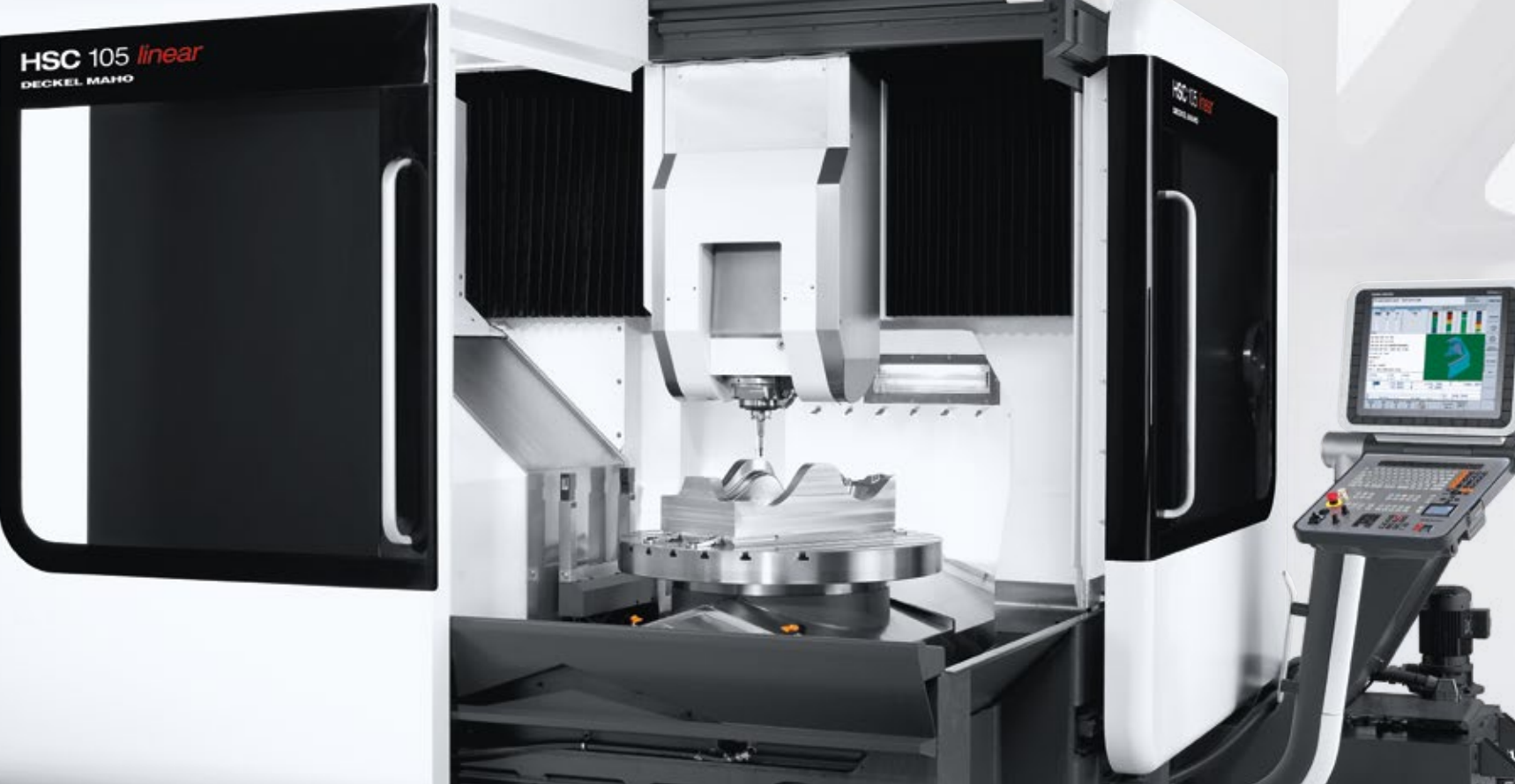
I am working on a Table Head (XYZ Head=B Table C) 5axis (DMG - Deckel) VMC Machine. (The picture is attached.
The Machine's forth Axis is C and Fifth Axis is B.
I use one Fixed Tool and Define it by "Tool CALL 0 Z S700"
But in 5 Axis operations. The Tool position is in wrong place.My questions:
Can I use Zero tool lenght, for this type of machine?
If yes, I'll need Define it in "HMI Tool Manager" or by "Tool Def " in PostProcessor?
Thanks
-
On 4/6/2021 at 4:34 PM, pullo said:
Very Nice
Thank you -
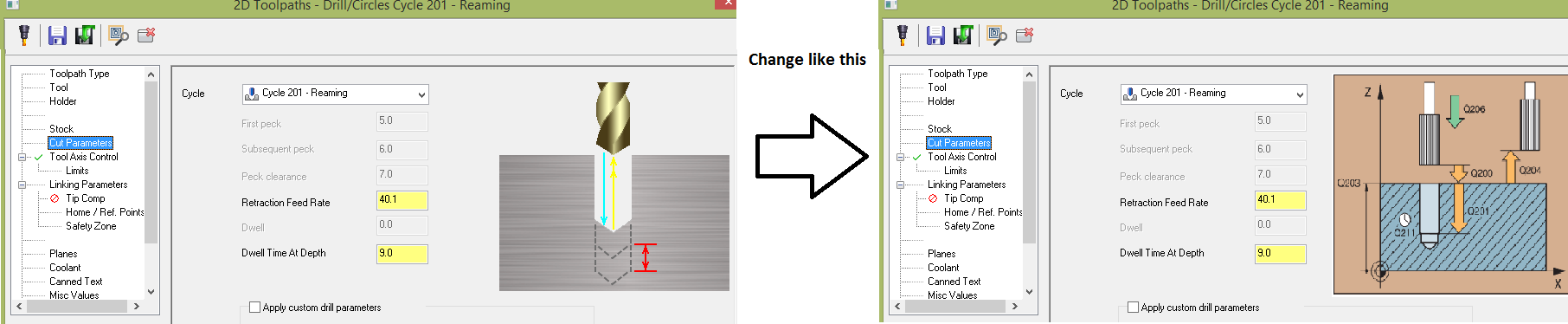
Hi
I'm looking for a way to change the Images, that describe the Cycles in drill cut parameter window.
Is ther any way to customize or change them.
Thanks for your attention.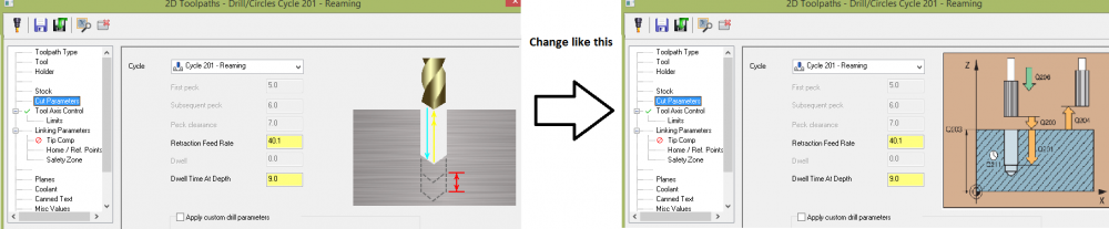
Dmu 50 post configuration
in Post Processor Development Forum
Posted
Thank you MillMan.
This is a challenge for me.
I think I am near to fix it.
I'd like try a little more