


TFarrell9
-
Posts
105 -
Joined
-
Last visited
Content Type
Profiles
Forums
Downloads
Store
eMastercam Wiki
Blogs
Gallery
Events
Posts posted by TFarrell9
-
-
In verify it showed the tool being rotated to the b90 plane even though you still had the toolpath set to the b270 plane?
-
What kind of advise are you looking for? Need some more information or we'll all just be throwing darts at a board blind.
What tools do you have available? What thread are you cutting? Where is the hole? IE: is it axial or radial? Radial thread milling cannot be done without a Y axis.
-
-
Your settings look correct.....I use this toolpath frequently and checking "rapid down" as you have yields rapid motion between pecks on all our machines. I'd send a Z2G to your reseller.
-
 1
1
-
 1
1
-
-
Here's a quick and dirty example (ignore speeds/feeds/doc) showing how multi-start and lead works. This example only works with a proper form insert (3tpi acme insert in this case), otherwise use custom thread as Craig suggested.
3 threads per inch with 3 starts effectively turns the lead into 1 thread per inch. Everything in the cycle is set for a 3tpi acme thread, save for Lead (in "thread shape parameters") and Multi Start. Lead needs to change from 3 to 1 because 3tpi/3starts=1 thread per inch per lead. Next, check the Multi Start option in "thread cut parameters", select the Multi Start button and enter your number of thread starts.
Because of how the tool will offset the amount of lead given for each start, your start position or acceleration clearance must be adjusted accordingly.
-
7 hours ago, bird2010 said:
Sorry I don’t speak English...


Thanks! I had never used Reflow UV before and I was trying to reflow all three surfaces together, rather than just the one....of course in hindsight, it makes sense to just do the one.
I've also used "single row only" in flowline, as I never knew what the purpose was. Turns out checking single row only and setting to spiral effectively blends the three surfaces together, cool!
Lastly, when I was trying Blend, I was chaining the curves along the surface and getting lift at the 45*. When chaining a projected flat curve, no more lift...interesting! I have even less experience using Blend as I do drawing surfaces, so I'm still figuring out how to chain the curves and set the Projection settings, both in toolpath control and cut parameters.
-
45 minutes ago, ajmer said:
Very cool, thank you so much. Before coming to the forum about this, I tried using Net but I kept getting a continuity error. Turns out I was chaining it wrong, most notably with the across curves.
I chained the surface without making a radius, just to see what it would do and it gave me a continuity error, but still created the surface and it didn't look warped. I opted to use a radius as you did though, as I'd rather not get any errors at all. Cool trick, same with the draft example you showed me before with turning it into a spline. I really appreciate your help.
Also for what it's worth, I was able to get fairly close to my desired motion with 3d blend, but as it came down the 45* wall it wanted to lift in some areas and plunge into the stock and with the angular lead-in/out control being limited, I could only avoid the plunge by giving it a combination of horizontal and big vertical lead-in. I also had to manipulate geometry a fair bit.
This net surface with flowline is clean and simple. Thanks again.
-
1
-
-
Well dang, the method worked great for creating the surface, but the flowline doesn't "sweep" along, so the toolpath wants to make linear motion. I tried to reflow the surface, but it warps the surface.
It's a bit cumbersome, but I think I'll have to offset copy the boundary curve to my desired stepovers, project the curves onto the surface, and use 3d contour. EDIT: Just kidding, that's not going to work either.
-
On 5/3/2024 at 5:05 PM, ajmer said:
take a look at this file
i created a silhouette boundary from the front
added a 0.001" rad in the corner to make the spline, next step, a little nicer
then created a spline from that
draft surface
then trimmed it from the top with the boundary i created
Really cool! Definitely not a method I knew of. Thanks!
On 5/4/2024 at 11:23 AM, crazy^millman said:Morph between 2 curves with no extra geometry created in a 3 Axis output and call it a day? Not exactly the same, but would get it done.
Sorry out of room to post a screen shot here is a link to the Dropbox file. I did try sweeping a surface and no luck. Ajmer has a good solution.
Would love to be able to do that, however I do not have the multiaxis package. Thank you for the effort though.
-
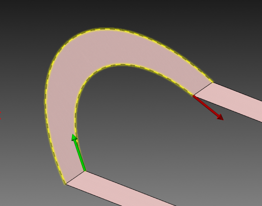
Attached is an operation from a file I made last year. I was able to make a single surface from the 3 solid faces and use a flowline operation that has worked really well and gives me the exact motion I want.
Another part with the same type of feature has come through and I can't for the life of me remember or replicate how I did it the first time. When I use Loft, it creates 3 separate surfaces, just as if they were the solid faces. I've tried everything I can think of with surface, solid, and mesh tools and I'm stumped.
I can tell I extended the surface because of some "wave" going on, but I can't derive anything else from it.
-
17 hours ago, Ben Wood said:
I tried adding all three values (XY & Z) on the G43.4 line but got weird undesired motion. I tried your second suggestion of using G43 inside the G68.2 call and that seemed to work. I tried it without changing the 5006 parameter and didn't get any Z motion with the G49. Is this the parameter I should change?
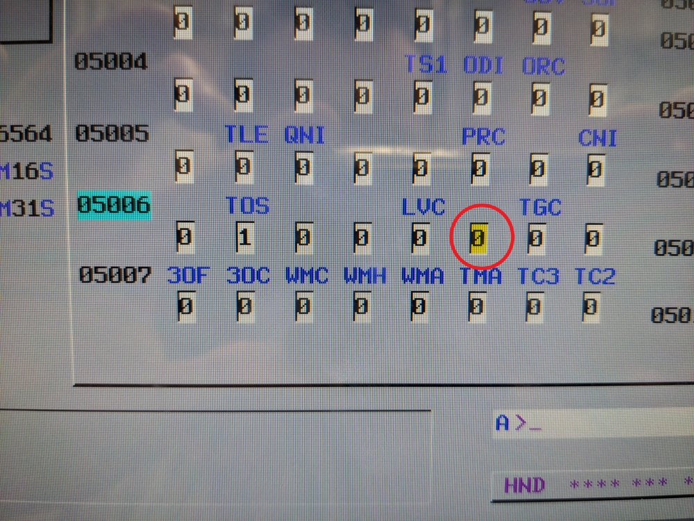
That's bit #2. Bit count moves from right to left, starting with zero. "TOS" is bit #6.
-
2
-
-
5 hours ago, Aaron Eberhard said:
This matches my settings, although I generally enable XZ & YZ arcs as well.
Also, for something like this, a Flowline toolpath works great.
I also like flowline for this, though I generally tend to use waterline instead (just more control) and set it to spiral.
sub-.0002" tolerance on the arc filter for a countersink is pretty wild, I'd also set it to .001" as previously suggested.
-
2 hours ago, Aaron Eberhard said:
Looks like perhaps the license file got stepped on/installed to a separate location? Eldar will get you sorted out pretty quick I'd imagine.
Eldar said he thinks it may be an issue with windows 11, but he'll have to do some troubleshooting.
-
I just realized that from within mastercam, it's still looking at the trial license, while the standalone app as seeing the purchased license. It all comes from the same app, doesn't it? I suppose I'll try reinstalling the plugin for mastercam to see if that works.
Edit: I've done a clean install of both the main application and plug-in and still have the same issue, I've contacted their support for help.
-
Howdy,
The 30-day trial expired, so we purchased the license. I'm having an issue when launching the app from within mastercam. It seems to launch fine, but when I try to select a different material (it's loading a different one than what I select prior to launching the full app) it gives me the pop-up in the attached screenshot. It has all the license info, but there is no "okay" to select or anything, and if I exit, it reverts the material selection. You may also notice is says "license level: trial 30", but has the purchased license info behind what I've blacked-out.
If I launch the app standalone (with mastercam closed), it seems to work as expected. Should I just try reinstalling the app or is there something I'm missing from within mastercam? For what it's worth, I removed the add-in from the ribbon and added it back in and there was no affect.
.thumb.png.d2017b51b5fd751060c60c193dfb3fb8.png)
-
Ended up getting away with breaking it up into two toolpaths and adding some avoidance blocks like Bird did. The pads close in proximity seem to be the where the issue lies, so I put some blocks around them and it came out okay, it's not ramping in anymore at least.
-
5
-
-
2 hours ago, bird2010 said:
if you don't want to change your ways
You can try to add entities (do not add boundaries) to make the software change the algorithm to eliminate rampBut...it's more correct to separate multiple operations
I've created avoidance bodies a fair bit with optirough to drive the shape I want, but I hadn't thought about applying it in this situation to see the effect. Thanks! I'll try breaking it up into a few paths and see if I can get what I want without creating the extra geometry first. Of course the less extra entities I have to create and move around, the better.
4 minutes ago, Jake L said:Which would explain the diamond shape on the pads. If there's nothing to avoid I think the toolpath just cuts straight along the x axis. Someone please correct me if I'm wrong on any of this
You're right, even some other pads that are in proximity to where its working around corners, it echoes the radius to neighboring pads. Meanwhile, other pads are left with linear, single axis cuts.
-
28 minutes ago, Jake L said:
That pretty much sums up why I don't like to use Area Mill or Area Rough. I'll try them to see if I get a good toolpath (no ramps), but often I'll just spend the time to make the extra geometry. Sometimes changing the min/max stepover can get rid of the ramps. But if the toolpath ends up with a blind "pocket" of material to take out I've never been able to stop it from ramping it.
In your sample it looks like the toolpath is morphing kind of weird because it has to go around the .200 high "walls". What I'd do is split that path into two or three paths. Maybe make all the square pads one path, then all the longer rails another path, and the rest a third? That should at least make the toolpath on the pads cut straight along one of the axis.
I don't know of a good way to fix it with a single toolpath. You could use toolpath editor but that comes with it's own pros and cons. And considering it looks like it took almost 3 minutes to regenerate the toolpath , I don't have the time to play with it too much.
You could try 2D Area Mill and see if that gives you better results but I imagine those two toolpaths use very similar logic to generate motion.
Off topic, but what on earth machine is this going in? The table and part are beyond huge compared to the work I typically see.
Same, I only use this toolpath for finishing faces/floors when I've previously roughed with optirough, since I only have to change a few settings that way. Otherwise, pretty undesirable to use.
I'll try breaking it up to see if chooses to not ramp the couple pads. As far as the diamond-shaped morphing though, it's done that before, just facing a rectangle with some avoidance in the corners, so I'm not sure what really dictates that shape, particularly on a surface with nothing to avoid.
OT: This is going in a Mitsubishi MVR 35. It recently replaced our old cnc-retrofit planer that had a 8'x40' table. The sacrifice in X travel was greatly compensated for by literally everything else.....the old one was only capable of face/drill/tap and mechanically it was pretty shot, and only 500rpm spindle lol We sent it to the scrap yard.
-
Howdy,
I'm looking for some advice when it comes to finish facing surfaces that have shoulders. I generally choose not to finish the faces of pads or bearing rails with optirough (even though this is a very simple way) purely for surface finish appearance. I often use 3D Area Rough for finishing these surfaces previously roughed with optirough and it pretty much always comes out the way I want.
However, sometimes it will ramp in the middle of surfaces (reminiscent of Horizontal Area), even with "from outside" control with "outside" compensation. It also seems to completely ignore my entry commands, even with steep/shallow min/max at the same depth, it will enter from 1/4"+ in the Z axis. This is particularly annoying when using a tool not capable of ramping.
Attached is a stripped sample file. I've noted two pads where it decides to ramp....seemingly completely random. I've tried expanding boundaries on these pads by a large margin and it still wants to ramp here. I also tried giving large "skip pockets" values and "apply leads" with no luck.
Anyone know of a good way to do this without having to make a bunch of extra geometry or a bunch of different paths? It's so easy to rough out, and surprisingly frustrating to finish some extremely basic surfaces.
-
Solids>Boolean>Add
Though if things aren't just right (overlaps, etc.), it won't work.
-
1
-
2
-
-
4 hours ago, cncappsjames said:
G05.1 is VERY picky about what is modal in activation/deactivation.
If I were a betting man, something is activated in your G510 MACRO that needs to be canceled. If you don't have access to the MACRO, cancel EVERYTHING between operations.
G00G17G40G80G90G94G98
G49G53P1Z0.0S11460M03
N30001(Contour Back Edge for Inspection Surface - 3:00 Face)
G05.1Q1
G00G90G54...
G43Z4.0H#517
...
G40Y2.5625
G00Z4.0
G05.1Q0
G00G49G90G53P1Z0.0I would try activating the G510 after the G54 or after the G43, the deactivating either before/after the G05.1Q0 or after the G49. That's where I'd start.
Be careful with G49. If parameters are not set correctly, you will get a Z- move the equivalent to the length of your positive tool length offset.
HTH
Good call on the G49, that's what it was. Thanks James!
-
2
-
-
This thread was revived at a pretty decent time for me, as I have a question pertaining to this function.
We recently acquired a Mitsubishi MVR 35 with a Fanuc 18i-MB control. This is the first machine I've touched that's had the G05.1 AICC function. In order to control the speed/accuracy setting commands for this one, G510 Mx (x=0,1,2,3) must be commanded before the G05.1 Q1. If not, AICC will still activate, but it will default to M0 for the finishing/"slow" setting.
Anyways, I'm encountering a problem after indexing the RAH. G05.1 Q0 is commanded at tool end, before the RAH indexes. However, when it gets to G05.1 Q1 again (after RAH index, same tool), I get Alarm 5111 IMPROPER MODAL G-CODE (G05.1 Q1). I hit Reset, start the program from the G510 line and everything goes on as it should.
I've tried adding another G05.1 Q0 before the G510 line, as well as a G80 for kicks, and no dice. I'm not seeing anything on the DRO for modal codes that would be causing this, so what could be holding it up? I know the mode is being cancelled because AICC no longer flashes after running G05.1 Q0.
-
I've been using my new pc for a week now and figured I'd update this with what I got and a toolpath generation comparison.
i9-13900k currently with base clock of 3.0GHz, 32gb 4400MHz DDR5, RTX A2000 12gb. Came in just under $3k from our third-party IT service.
Just in general use, opening and closing files, even moving geometry around on the screen, this pc feels leaps and bounds above what I was using. Loving it so far.
There was a toolpath that took just over 17 minutes to generate on the old computer, the same toolpath can be generated in just over 2 minutes with this one.
Thanks again for the input!
-
1
-
-
2 hours ago, Kyle F said:
embarrassingly enough I just recently figured this out, in all my old programs I would go in and manually break wireframe geometry to remachine radii lol... sometimes I surprise myself
Even better/easier than that is Dynamic Contour or Optirest.
-
1
-

.png.fe8e0e1d868b3a4a24f7c0f927feba1f.png)
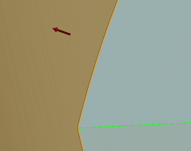
Missed collision in verify
in Industrial Forum
Posted
I'm curious because I'm not familiar with this Line method of axis control, can you share a sample file? I've always treated single offset programs the same as multi offset programs, only forcing all the work offset outputs as g54.