


CoonDogWillie
-
Posts
6 -
Joined
-
Last visited
Content Type
Profiles
Forums
Downloads
Store
eMastercam Wiki
Blogs
Gallery
Events
Posts posted by CoonDogWillie
-
-
On 4/22/2008 at 12:05 PM, crazy^millman said:
Got a good one for you. Make a 1/2 endmill work like a chamfer mill. Seems they did not pay attention to the tool list, program note, or the fact that it scrapped the part. Oh the the fun begins about how stupid a programmer I am and how I make bad programs and everyone loves to tell the owner I made a mistake, yet when someone else makes one they never fess up. I pretty much let it be known today I got big shoulders and if I were let go because the perception is I can not do my job because of others people mistakes I can find me a job tomorrow can you? No comments imagine that. graemlins/cuckoo.gifgraemlins/cuckoo.gifgraemlins/bonk.gifgraemlins/bonk.gifgraemlins/banghead.gifgraemlins/banghead.gifgraemlins/headscratch.gifgraemlins/headscratch.gif
I'm with you Brother. Although it sounds like you handle it better than me. I usually decline to comment rather than get into a back and forth. Mainly because it seems like an operator can xxxx on the floor and not get into any real trouble, at least over here in Wisconsin.
It usually gnaws at me so it makes me think, Dude! I started way WAY back on the floor. I've done you're job as a button pusher/operator (depending on the individual when a situation happens) Now, as a manufacturing engineer my job involves CIP's, Programming, Fixture Design, Procurement, etc. You're over here acting like you're a Damn Genius and the reason this tool went through the part and into the table is because I did something. NOooo! it had nothing to do with you not touching off a tool correctly.
-
 1
1
-
-
On 2/27/2023 at 1:38 PM, crazy^millman said:
Here is what Tim Markoski shared years ago.
Thank you SO! much Tim Markoski, I just downloaded, haven't checked them out yet but, I trust they are legit.
The files will really help.
-
Thank you so much for your response! I get somethings together and post asap. It's another busy day at the salt mines.
-
Would anyone know a resource, pay or free at this point I will feel blessed to be able to find something that could get me to understand how to judge and decide which of the many 2 or 3 D strategies MS has available is the one I should select. At least I would be love to be able to narrow it down to 1 or 2.
Also I like to find instructions more specific or to the point. Like a step by step break down of approaching programming of a solid model. I have watched the "my mastercam" courses, "mastercam core" , "2D mill" and although nicely done it is very broad.
You can look at the file I have attached. I was asked to mill a groove on the inside of a hole clocked at 3 and what you see is the best I could do. Darn pathetic I know BUT, I will do whatever I need to in order to get so I understand this.
PLEASE any help sent and "your a good kind person someday people will wright songs about" that's what i'll say to anyone and everyone whether they care to listen or not

-
I wanted to build a solid model tooling library and start using them to verify my toolpaths. From what I hear it's the greatest thing since... yes, sliced bread.
Shortly after I began the process I got frustrated. I must be doing something wrong. I ended up following along with a youtube
After going through the tuts import process I can't believe it's correct although the results are better that what i get when I pull the tool solid moder in.
 This is the result the tut on youtube showed after import.
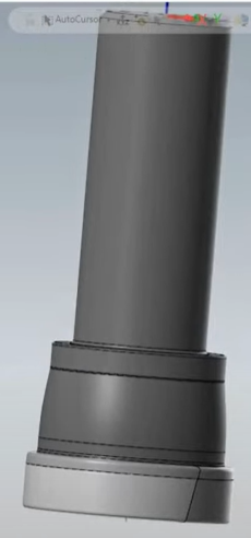
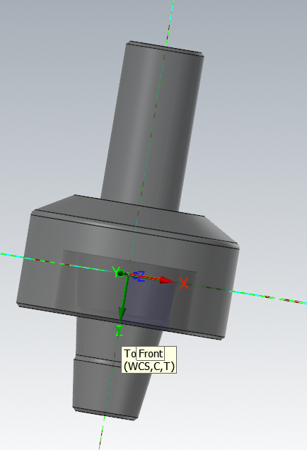
I downloaded a GTC package, a DXF, and a 3d step from sandviks site and got THIS. This is what should be the model for a keyseat/slot mill cutter. I would expect the solid model to show the inserts or some sort of detail. Please, tell me where I went wrong and what I can do to achieve a better representation or if this is the best case scenario please let me know I drank the kool-Aid and yes, this is the big let down.
DRILLING HOLLOW SQUARE TUBE
in Industrial Forum
Posted
Thanks, I didn't pay attention to the date of the post I think it's older but, it helped