


RACINGCONVERTERS
-
Posts
101 -
Joined
-
Last visited
Content Type
Profiles
Forums
Downloads
Store
eMastercam Wiki
Blogs
Gallery
Events
Posts posted by RACINGCONVERTERS
-
-
Following the steps from GCode seems to have worked like I wanted.
I have been looking for the advanced drill cycle, I have yet to find it or how to find the advanced features of the drilling. Can anyone point me in the right direction on that, to further my knowledge.
-
Drilling cycle
-
That option is greys out in the drill toolpath I have.
-
I was able to adjust the post to not post the cycle. Thank You for the help.
One more question! Is there a way to change to post fast feed instead of rapid?
-
Is there a way to change from using a G81 drill cycle to a point to point drilling. (not using cycle syntax)
-
I have had experience running Zimmermann machines. They are built to be fast light cut machines. If you keep that in mind they are very productive and can make you a lot of money. If you order new, almost anything you think of can be an option. Vacuum, hydraulics, etc.ect...
-
They were oriented correct. I would assume that it is the file quality. I tried several different ways to import the STP. Finally was able to make it work by bringing in the rendered model with custom export directly into the tool manager. Then it did not have the proper gage line and the tool was not in the correct spot.

-
Thank You Sir!
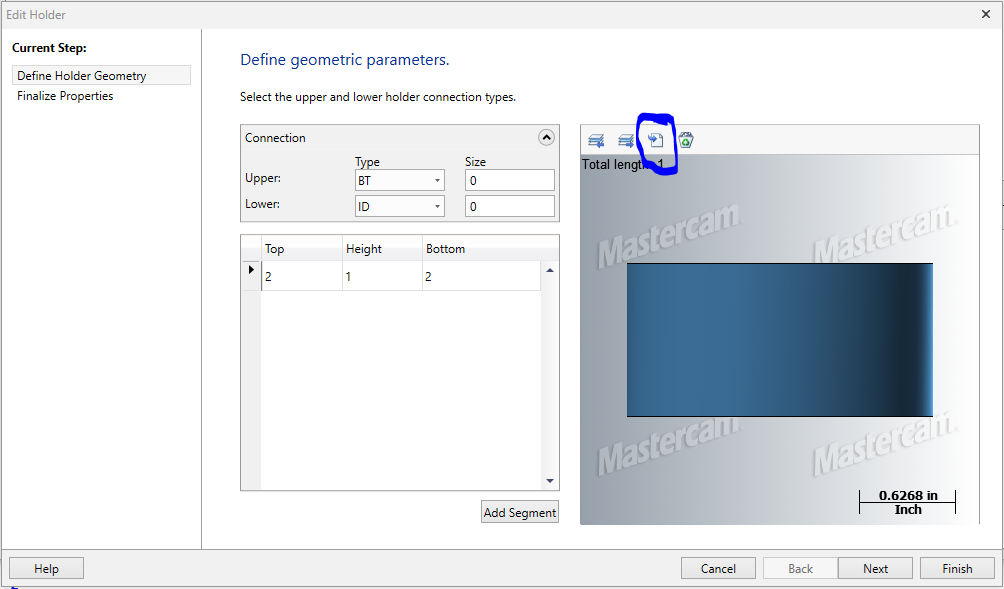
Are many people using the Machine Cloud App.? I have been playing with it today and it seems the tool holders do not import properly. Has anyone else tried this?
-
Gents,
I have tried searching and reading the help file and cannot seem to figure out how to create a tool from an STP. I have downloaded the STP from the manufactures website and when I try to use import on the new tool page I only have the option for DXF. Can anyone help me out?
Matt
-
Thank yo for all your help on this. I went with checking the pins at B0. for deviation from location to and averaged the three pins deviation to get the location. It is not the best but it is getting the job done.
-
The pin circle has to be close. It is usually held to +/-.001 because the holes are part datums.
Again thank you for your help.
-
Thank you Husker
Using the formula you gave me this is what I have got. Not sure how to take the formula you have given me and put it in as Macro B. Would you or anyone be able to share with me how to do this in Macro B? N40 is the calculation section. I entered the formula next to it. I understand the math not Macro B formulas so much. This is to save time on setup from tramming it in with an indicator. System has over 100 pallets to calculate center on for setup.
O8600 #630=0 CLEAR VARIABLES #631=0 #632=0 #633=0 #634=0 #635=0 #636=0 #637=0 #638=0 #639=0 #640=0 #641=0 #642=0 #643=0 #644=0 #645=0 #646=0 #647=0 #648=0 #649=0 #650=0 #651=0 #652=0 #653=0 #654=0 #655=0 #645=0 #657=0 #658=0 #659=0 #3006=1 SET VARIABLE VALUES (ENTER VARIABLES BELOW) (#630 = Diameter of Bolt Circle Feature is on) (#631 = Diameter of Boss or Bore) (#632 = Use when a BORE is Measured) (#633 = Use when a BOSS is Measured) (#634 = Angle of First Boss or Bore) (#635 = Angle of SECOND Boss or Bore) (#637 = Angle of THIRD Boss or Bore) (#638 = ABSOLUTE Z REFERENCE OF SURFACE BOSS OR BORE IS ON) (#639 = ANGLE OF SURFACE TO MEASURE Z) T1 STANDARD PROGRAM START M06 G17 G40 G49 G80 G91 G28 Z0. G0 G90 G54 X0.Y0. A0. B0. G43 H1 Z10. M01 G0 B#639 POSITION B0. TO SET Z SURFACE X[#670/2] Y0. POSITION X AND Y TO PROBE POSITION G65 P9832 PROBE ON G65 P9810 Z[#638 + 2.] F100. SAFE MOVE TO Z+2. G65 P9811 Z0. R2. PROBE Z SURFACE LOOKING 2" IN ADVANCE G65P9833 PROBE OFF #640=#137 SET VARIABLE #640 TO Z MEASURED VALUE G0 Z5. F100. Z CLEARANCE B0. POSITION B TO 0 X[#630/2[COS[#634]]] Y[#630/2[SIN[#634]]] POSITION X AND Y TO FIRST PIN IF[#672EQ1] GOTO N20 LOGIC TO DETERMINE IF A BOSS OR BORE IF[#673EQ1] GOTO N10 #3001=1 (NOT ENOUGH INFORMATION TO CONTINUE) N10 Boss Probe G65 P9832 PROBE ON G65 P9810 Z[#640+1.] POSITION Z ABOVE PIN G65 P9814 D#631 Z[#677+.2] R.25 MEASURE PIN G65 P9833 PROBE OFF #641=#135 STORE X VALUE IN #641 #642=#136 STORE Y VALUE IN #642 G0 Z5. F100. Z CLEARANCE X[#630/2[COS[#635]]] Y[#630/2[SIN[#635]]] POSITION X AND Y TO SECOND PIN G65 P9832 PROBE ON G65 P9810 Z[#640+1.] POSITION Z ABOVE PIN G65 P9814 D#631 Z[#677+.2] R.25 MEASURE PIN G65 P9833 PROBE OFF #643=#135 STORE X VALUE IN #643 #644=#136 STORE Y VALUE IN #644 G0 Z5. F100. Z CLEARANCE X[#630/2[COS[#636]]] Y[#630/2[SIN[#636]]] POSITION X AND Y TO THIRD PIN G65 P9832 PROBE ON G65 P9810 Z[#640+1.] POSITION Z ABOVE PIN G65 P9814 D#631 Z[#677+.2] R.25 MEASURE PIN G65 P9833 PROBE OFF #645=#135 STORE X VALUE IN #645 #646=#136 STORE Y VALUE IN #646 G0 Z5. F100. Z CLEARANCE GOTO N30 N20 BORE Probe G65 P9832 PROBE ON G65 P9810 Z[#640+1.] POSITION Z ABOVE BORE G65 P9814 D#631 MEASURE BORE G65 P9833 PROBE OFF #641=#135 STORE X VALUE IN #641 #642=#136 STORE Y VALUE IN #642 G0 Z5. F100. Z CLEARANCE X[#630/2[COS[#635]]] Y[#630/2[SIN[#635]]] POSITION X AND Y TO SECOND BORE G65 P9832 PROBE ON G65 P9810 Z[#640+1.] POSITION Z ABOVE BORE G65 P9814 D#631 MEASURE BORE G65 P9833 PROBE OFF #643=#135 STORE X VALUE IN #643 #644=#136 STORE Y VALUE IN #644 G0 Z5. F100. Z CLEARANCE X[#630/2[COS[#636]]] Y[#630/2[SIN[#636]]] POSITION X AND Y TO THIRD BORE G65 P9832 PROBE ON G65 P9810 Z[#640+1.] POSITION Z ABOVE BORE G65 P9814 D#631 Z[#677+.2] R.25 MEASURE BORE G65 P9833 PROBE OFF #645=#135 STORE X VALUE IN #645 #646=#136 STORE Y VALUE IN #646 G0 Z5. F100. Z CLEARANCE GOTO N30 N30 G91G28Z0. Z CLEARANCE N40 CENTER CALULATION (#641-Xc)^2-(#642-Yc)^2-R^2=0 (#643-Xc)^2-(#644-Yc)^2-R^2=0 (#645-Xc)^2-(#646-Yc)^2-R^2=0 (#643-Xc)^2-(#644-Yc)^2-R^2-(#641-Xc)^2-(#642-Yc)^2-R^2=0 (#645-Xc)^2-(#646-Yc)^2-R^2-(#641-Xc)^2-(#642-Yc)^2-R^2=0 CENTER OF X SET TO #657 CENTER OF Y SET TO #658 #7001=[#5221-#657] SET VALUE OF X TO #7001 #7002=[#5222-#658] SET VALUE OF Y TO #7002 N50 M30 -
I am trying to right a probing macro to determine the center of three pins that are not a simple 120 degrees apart for fixture offsets. The pins are equally spaced but not to a three pin configuration. Example: I may have 5 holes equally spaced on the part setting them at 72 degrees apart, the fixture uses three pins to locate the part. The first pin maybe 20 degree, the second at 92 degrees , and the third at 236.
The information I have is as follows.
Diameter of bolt circle
angle that each pin is on
I tried to write a macro program using G65P9819 from Renishaw but it will not work because I am only wanting to measure three pins not the five. I am needing to probe each pin, store the variables for x and y as I probe each one, run a calculation to determine the center of them. The problem is I am not sure what that calculation is. Would anyone be able to help with this.
Thank you in advance.
Not asking for a program, I can write that. I just need a little help with the mathematical side.
I should probably add this is a 5 axis trunnion machine, and the fixture is not trammed to the center of the rotary Axis, Wanting to know what it is off for the dynamic fixture offset.
Matt
-
I had some made by the 80/20 guys. It is expensive but they could support several thousand pounds of parts and people and can be fully customized to fit your need
-
I am using X+ tool list to create setup sheets. In my file I use one machine group and a new toolpath group for each position. So I use the c-hook create the Html then choose edit in word and save it as a word document for each position. When I go back to the first one to print it; it has the screen shot from the last html made. Can anyone tell me why this is? I don't recall it doing that before, but the last few parts it has.
Thank you
Oh yeah this is in X4
-
To start I am new to 5 axis and to 90 degree heads. I did a search on aggregate heads and found very useful information from other posts and the ftp site.
I followed the direction from the folder on the ftp site and created an aggregate 90 degree head.
The machine this is going on is a SNK verticle 5-axis with +/-25 deg. on the a and b. The hole I am machining is at 99.8 deg, this is why I need the 90 deg. head. Also on this machine we do not run any tool lenth offsets. With the post I have the pivot distance and tool length have to be added together and put in when prompted.
With all that said I made a contour with the 90 deg. head at 9.8 deg and it looked right. I posted; when promted I put in pivot distance of the machine and length to centerline of the cutter, and the results added that value to the x axis.
If I am understanding this correctly now I have two pivot distances and gage lengths that have to be controlled. How and where do I do this at within mastercam?
Thank You in advance any help is greatly appreciated
-
Can anyone tell me why when I try to import my nci it takes along time and usually haults execution. Which shuts down MC.
-
I tried to use it with no luck but I may have been doing wrong.
-
Lars ,
We have Cimco for DNC but the guys on the floor do not like it because they can not see the next move on the screen. So I am haveing to guess at how many operations will fit, post and then change accordingly by adding an operation or taking one away.
-
Lars ,
We have Cimco for DNC but the guys on the floor do not like it because they can not see the next move on the screen. So I am haveing to guess at how many operations will fit, post and then change accordingly by adding an operation or taking one away.
-
I have a machine that on has 49kb memory and need to keep my programs smaller to fit. Is there away to make several smallprograms out of a large program?
Thanks
-
I have received this error when I have a comment string that is to long. But I can usually reset and the go to edit and change what needs to be changed
-
Thanks John
-
We have 1.7.2.1.
What is the latest until 12/08
because that is when the maintenance was up.
Drilling without using a cycle
in Industrial Forum
Posted
Thank you GCode. I am using 2020 currently. I can upgrade I just haven't.
I should probably change my siggy.