


Mr. Wizzard
-
Posts
739 -
Joined
-
Last visited
Content Type
Profiles
Forums
Downloads
Store
eMastercam Wiki
Blogs
Gallery
Events
Posts posted by Mr. Wizzard
-
-

Boom, fixed......
-
Great information Brad, thanks so much!!
-
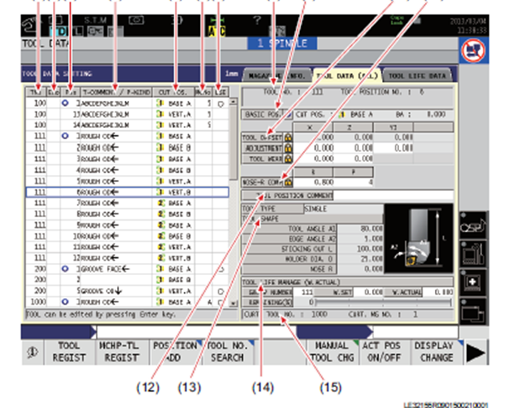
Can anyone tell me the difference between X/Y/Z Adjustment and Tool wear?
I'm looking at tool data for an Okuma Multus and I cannot find any information in the manuals that really describes the usage, application, or behavior of "tool adjustment" vs. "Tool wear."
Any tips would be greatly appreciated!!!
-
ok, just checked an X6 file in X8.
Under "rotary axis control" in operation, set to C axis.
In backplot options, check "simulate rotary axis".
in backplot, it works fine and clears.
In verify, it drags through the part.
Same settings, run in X6, no gouge in backplot or verify!!
-
check your b-plot/verify settings for stuff.
i think it's called "simulate rotary axis substitution".
-
what do you have set for "axis control" in your operations?
i set that and always get my rotation output. od thing is, i have to have it "off" on a drilling cycle to get it to post rotation.
and, dont mean to be too technical, but it's your t-plane that will give you rotation, not wcs. if they match, no rotation.
-
I've had pretty good luck with Horizon inserts when i had issues breaking a chip in aluminum. Don't be scared, though, you have to push them! The right coolant helps so it doesn't stick to the insert also.
Also, depending on the machine/control, some canned cycles (G74 i think) can peck turn, but only straight geo, no arcs/curves.
-
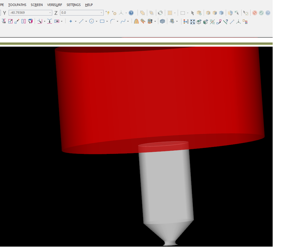
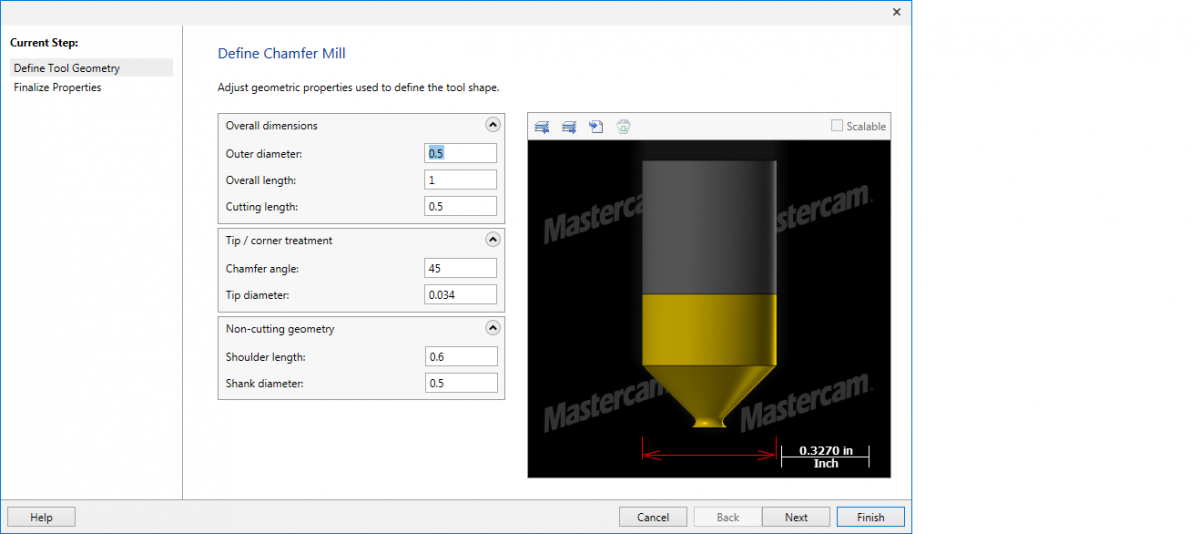
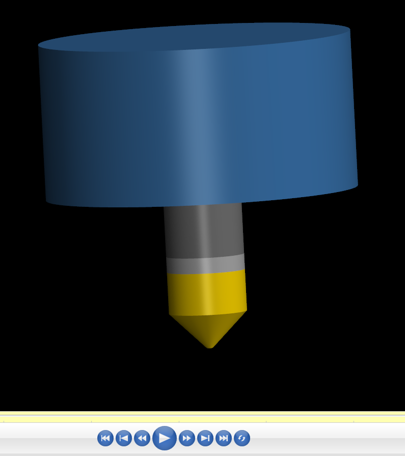
Ok, so same chamfer tool in X5, X6, now X8.
What's up with the tool manager profile vs the backplot profile vs the verify profile?
It looks correct in verify, NOT in tool manager and backplot.
Any ideas???


-
If I understand correctly, you should be able to restart prior to the codes above being read, but not afterwards.
what I mean by that, is the machine needs to read those codes in order to run/calculate correctly. Since those codes are typically recalculating positions and feed rates at every line of code involving movement, you probably cannot skip down through moves and have it just pick up and know where it should be.
In these circumstances, you can probably only start at tool change positions where these are typically set and read.
-
billb
I tried changing the filter to 35% cut 65% filter and that fixed it and gave me a 25 second regen time.
Also, I changed the scallop height from .005 to .002, just to make sure it was crunching.
that did speed it up, however, I'm curious as to why?
I'll have to try on the old computer later to get a comparable time, as I think it will run faster.
I'll keep experimenting, thanks.
-
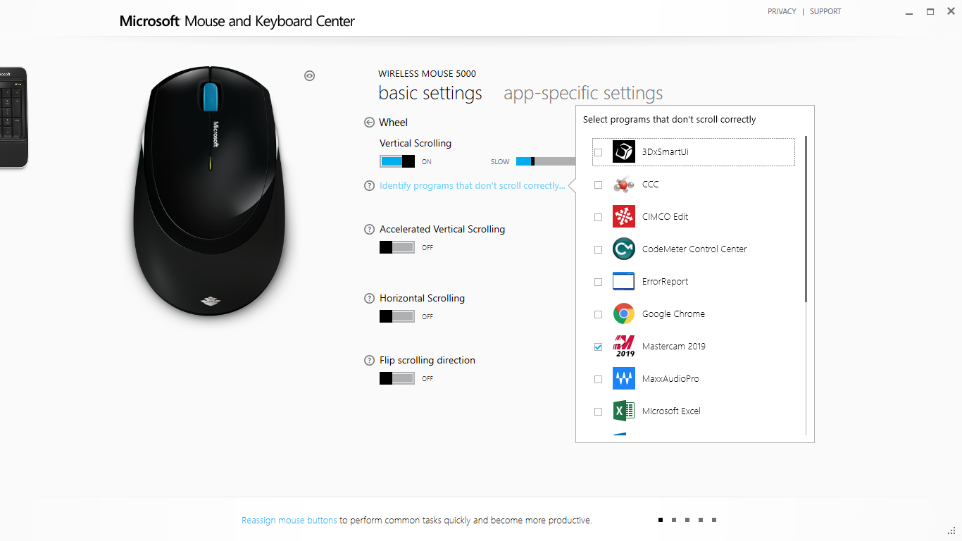
where do I do that?
-
Yep, just a quick sample I made.
Operation 1 is unfiltered.
Operation 2 is the same toolpath, but filtered. = 6 minutes 40 seconds to generate.
-
Surface finish flowline, one of my personal favorites.
Tried same toolpath in X7, got bored watching it think for 5 minutes and closed it.
In the past, this toolpath should have taken no more the 15-20 seconds, tops.
-
It doesn't appear to be using all 8 cores, though, only 4 of them.
And why would they work faster on an older computer than a newer computer? If I run the same thing on an older one, it's much faster.
it's not a tough toolpath, but takes 7 minutes to regen. i'll try in X7 and see what happens.
-
So, I've got a new pc going, details in signature.
Running X6 MU3 and doing surface toolpaths.
When it's calculating one, the CPU usage won't go over 13% and locks up mastercam. Many times I close it, after waiting 15 or 20 minutes.
How can I get my processor to "work" more and get this thing sped up?
Am I incorrectly assuming this thing should fly or do I need to adjust settings somewhere?
Any help would be greatly appreciated, as I am no IT wizard

-
no duplicate entities
no broken chains
plane defaults to top for c-axis contour
what I can't figure out is, if the toolpath comes out right, why the alarm?
-
ok, sorry I haven't been here for a while, but I need some help.
I'm doing a c-axis contour around a diameter and the toolpath seems to come out correctly, haven't run the code on the machine, but it looks ok.
It backplots fine, verifies fine.
Using X6MU3.
every time I regen the toolpath or do one from scratch, I get the error "warning - zero length line" and have to hit "ok" to proceed.
- is there a reason this happens that I can avoid it?
- if it has no effect on the toolpath, why does it come up?
as always, any help is greatly appreciated.
-
i use FBM (Feature Based Mowing) and have my son do it.
It never matches the print and it's different every time, but if the machine didn't crash and i didn't have to do it, i call it a win.
-
 3
3
-
-
Funny cause it's true:
----------------------------- I always read the superstition topic when it comes up from time to time, just to make sure i'm not missing any..................
-
Top drop down, machine type, lathe, manage list
-
Still using X6, but i know that my tool table won't post on one of our machines if any tools are set to carbide. It will only post the tools in the tool table at the top of the program if they're set to HSS.
-
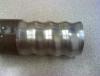
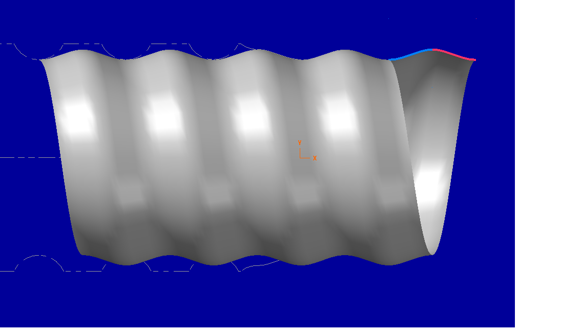
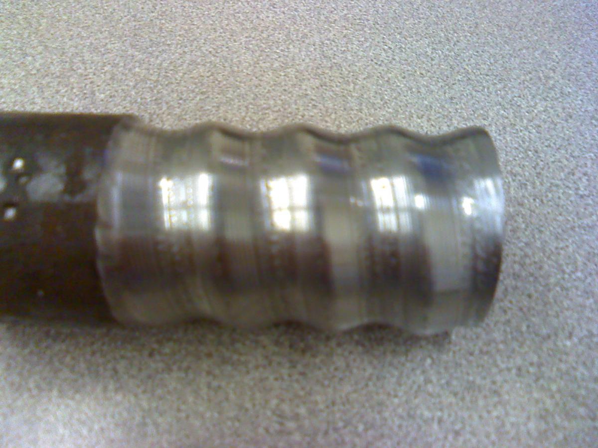
Regular 2-axis lathe.
.313 wide full radius insert
I did my test part on the OD, so i could see what was going on.
Here's the process;
1- create the geo, surface optional, but i like the visual
2- offset the chain .1565 (radius of the insert)
3- create spline from curves, chain offset geo
4- break spline (picked .025 segments)
5- create points at segments (ended up with 22 points for 1 pitch)
6- create threading toolpath, select first point for "minor diameter & z start point", comp tool to center of insert
7- copy toolpath 21 times, change minor diameter & z start point to each of the other points in succession
8- post so you get G32 cycle at each start point
9- set up tool and increment your "Z offset" +.1565 and your "diameter offset" -.313 to bring the tool tip to the finish geo
10- run part and be amazed
I need to tweak some things in, maybe smaller steps and multi-passes, but overall i'm satisfied with the first trial


-
4
-
-
Mildly time consuming, but i think i nailed it. May need to tweak, but that's why i'm The Wizzard!
I'll share details later.
RayD, sound like a good thing to try. I may look into it later just to see if there's a better way. Definitely a good idea, though.
-
Keith, thanks, but I don't think another software is an option right now. It does look like the way to go, but this may be a one off thing. I don't have a lot of information on the job yet.
Robert, wow. That sounds amazingly complex. I'm sure we'll have to go with a round button style insert, but i don't how to approach it just yet. I'll keep you posted on my progress. Please do the same and hopefully we can help out anyone else that may come across this.
Thanks guys, i'll let you know.


Okuma OSP-P300LA (Looking for simple intructions on creating a master tool)
in Industrial Forum
Posted
Titanium, this should be all you need.
LATHE TOUCH SETTER CALIBRATION AND BASE ZERO.pdf