


dylskee
-
Posts
43 -
Joined
-
Last visited
Content Type
Profiles
Forums
Downloads
Store
eMastercam Wiki
Blogs
Gallery
Events
Posts posted by dylskee
-
-
I have noticed this too, but only when running MC on a horrible Dell Costco special.
This is happening on a couple high end I7 setups, I'll play with some graphical settings and see what I come up with.
-
Change the tool tolerance in the options page The default value is .008, which is pretty rough
I tried that but it didn't seem to help that much...... Another strange thing I noticed when using stock models is when I regenerate an operation I see a wireframe of the entire model, what causes this? It only happens when I have a stock model within my file though.

-
Off topic here but where can I adjust the Verify settings to get a better looking stock model? I create a solid for most of my stock models and when I go to verify it's all faceted and looks like crap! It's not a huge deal but I would be happier if I could make it look a little better, it looks great in GibbsCam or Solidworks but looks horrible in MasterCam.
-
I just did a bunch of back chamfering with one of those. I had to end up using a 2D contour toolpath and fart around with the depths until it came out right. I don't see why one couldn't use a chamfer toolpath, I just couldn't/wouldn't make it work.
I actually did what Jeff suggested and it worked perfectly. I just defined the bottom half of the chamfer mill and used the 2D chamfer setting my tool tip as low as I could get it so I could use the largest dia possible.

-
I'm setting up a job that I use a double angle chamfer mill to break some edges and I was wondering if it were possible to use the 2D chamfer option with a cutter of this type or do I have to use a contour instead? I made a custom tool and used "Undefined" and I get an Invalid Tool Type error when trying to generate the tool path. I use these types of cutters when I have to deburr a step I mill up to a shoulder, just wondering if I can use the 2D chamfer or am I going to have to use a 2D contour?

-
Thank you very much, that was getting annoying.......
-
One thing that has been driving me nuts lately is when I create a new WCS using the "Dynamic WCS" and try to dynamically rotate the part it snaps to the default view and becomes very hard to view. Why does this do this with custom views? If you use the standard views it doesn't react this way, why?
-
Dylskee your back to M.C.? I thought you went back to gibbscam.
Hey Dtm, I use Gibbs at my day job and MasterCam at my part time job.
-
Oh man, I haven't done the 4th op yet!!! That's why it looks like it's taking too much material, I haven't flipped the part and cut that last slot. Sorry, it's been a long week man!
 I verified the tool path to the solid and it was fine.
 -
do you mean its cutting too much out on the machine..
you have the origin of OP3 set on the back corner of the part.
It you're setting your machine zero there you should be getting a good part.
I haven't cut it on the machine yet but the verify shows the part cutting too deep. Run the verify and then look at the solid, it's cutting too deep for some reason.
-
Hey guys, having a problem with a WCS that I have set at a 45° angle using the WCS from Face. It's just a 45° step that I'm milling but it's cutting way to deep for some reason. I'm picking the surface for my depth but it's chopping it way too much. Can someone take a look at my file and tell me where I'm going wrong? Thanks in advance......
EDIT: Sorry, it's op 3 in the view manager and level as well.
-
Create an edge curve on each side of the gap, then use create=surface=ruled
Thanks Hardmill, I don't really use mastercam much for solids so I'm starting to play around with it now. Thanks for all your replies.

-
 1
1
-
-
Here ya go,
Filled the solid notch, cut the radius and created new surface
Thanks buddy! I was trying to do it within the "create surface" area.
-
Is this what you wanted ??
Yes and no, I wanted to make the radius look just like the other side but what you did would work as well, now how did you do that???

-
Here you go......
-
Hey guys, I'm not too familiar with the surface tools in MasterCam so I was wondering if someone could help me out with extending a surface to another surface? I have a part that I have to mill a slot and then do some surface machining but the surface is disconnected on one side but I want the tool do surface both sides the same, how do I connect a surface to another? I'll post a screen shot of the surfaces, I need the surface to connect like the right side.

-
How do you use the 4th axis simulation for the part and not the tool? I'm using a solid model I created for the stock model and I choose the solid from the verify options but it just shows the tool moving about the axis. I have a model of a 2 jaw chuck with special made jaws that I use for my 4th axis simulation so I can watch for interference and really tweak my tool length out of holder for rigidity purposes. It seems the only time I can have the part simulation is if I use the "Initial stock size source" and specify a cylinder diameter, this is where I would like to select my stock model.
-
We currently use an old software and cam cutter to make cams for our Tornos screw machines. Is anybody using mastercam to generate these toolpaths? Seems like there would be some sort of cam C-hook or something.
Why would there be a C-hook for a basic contour operation??
-
I never knew I could get it to machine both ways, learned something new today! Thanks!
+1
Man, learning the little things really help!
-
Merry Christmas to all.
-
This place is ridiculous, it really is!
-
1
-
-
Check out the Rolldie chook for things like this,
You'll notice I offset the lines half the diameter of the cutter, drew a lead in/lead out line, chained as a partial with wait turned on so I could choose each section and have it remain as a single chain. Comp is off
Thanks guys, got the job going but had to rotate the part -90° in MasterCam to get it to cut in the proper orientation in the machine. Where do I find this "Rolldie C-Hook"?
-
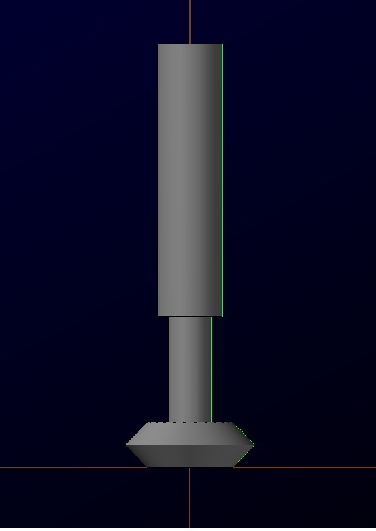
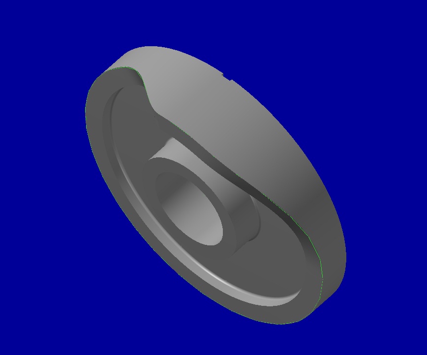
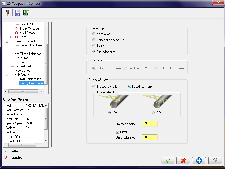
Hey guys, looking for a little help with a 4 axis job that I'm working on. Tomorrow is my last day with this company and the owner is away for a few days and I'm trying to get this job done for him. I have a couple of cams to cut and the profile is on the face, I selected the face surface and extracted the geometry and when I set all my parameters I selected the box to "Unroll" in the contour process. It backplots perfect on the screen but the part seems to be cutting 180 degrees from it's starting point in the machine. I have done a few 4 axis jobs in this machine with the same post but this one seems to be screwy.
Do I have to unroll the geometry before applying toolpath? Thanks for any help you can provide.
EDIT: I've uploaded the file to the FTP in the X5 directory, called "CAM"

-
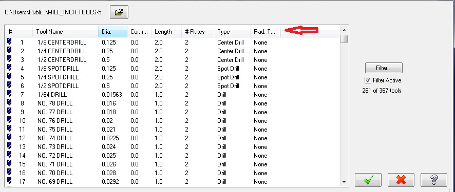
I know this might seem too simple but You never know......
Hover your mouse at the top of the toolbar where the columns are and drag the columns to the right, they might just be collapsed to the left. I'm guilty of it sometimes myself.


Job Tracking and costing software
in Industrial Forum
Posted
We use JobBOS but it's pretty pricey, I know guys that just use an excel sheet and it's just as effective.