


SledGeek
-
Posts
579 -
Joined
-
Last visited
Content Type
Profiles
Forums
Downloads
Store
eMastercam Wiki
Blogs
Gallery
Events
Posts posted by SledGeek
-
-
Hoping this is a good place for the problem.
I am currently running X8. I just received X9 disc and installed it successfully, however, it won't open.
I get " The program can't start because mfc120.dll is missing from your computer. Try reinstalling the program to fix problem"
I have reinstalled from disc on online several times with no luck. The dll exist on my C: but I'm wondering if it needs to be somewhere else as well? Or maybe mcam just doesn't see it?
W7 Enterprise on HP Z400 Workstation
Any thoughts?
-
Heh, probably. But at this point , I'm just guessing and thinking out loud.
 I will try the tilt, thnx
 .gif) This the first toolpath I am trying with multi.
This the first toolpath I am trying with multi.Since I just got the multi axis, I'm more like a kid in a candy store that can't figure out why licorice won't fit in my mouth just cuz there's 10 tootsie rolls there already.

-
Big difference with unroll unchecked ! In looking at this again, I can get it to cut around that boss, but this really isn't a axis substitution toolpath. When viewing from the side, I realize that it would have to be a full 4 axis as the y needs to make a linear move at the same time the 4th is turning until it gets back to c'line at which point it can rotate. I would love to figure this out in one cut, but I beleive I will need to do two for now, and blend them.
Make sense?
-
Ok, thanks guys. I will try this mkd and also investigate different toolpaths . Maybe I'll get lucky until I figure this stuff out
-
I had posted this in industrial but maybe this is a better place for it. I am trying to cut a releif on a cam, but not having much luck. It verifies nicely but will not cut properly. I am not sure if this is a post problem or programming problem. Everything looks good until cutting.
I am using X8 with multi axis on a Oi-MC control. All the rotary positioning works fine but the axis substitution is not. The tool comes down to the start point at what appears to be 180 degrees off and then rotates the wrong way.
If you look at Clearance toolpath group there are 2 axis substition cuts. They are the clearance cuts I am referring to.
Sorry for double posting this in both forums....kinda desperate.
IMG_0349.MOV Z lock on and only shows first cut.
(T15 - 0.49 FLAT ENDMILL - H15 - D15 - D0.4900")N100 G00 G17 G20 G40 G80 G90N102 G91 G28 Z0.N104 (COMPENSATION TYPE - COMPUTER)N106 T15 M06 (0.49 FLAT ENDMILL)N108 G00 G17 G90 G54 A106.011 X.87 Y0. S3056 M03N110 G49N112 G94N114 G05.1 Q1N116 G43 H15 Z1.925N118 Z1.275N120 G01 Z.55 F5.N122 G93 A-130.014 F20.23N124 G00 Z1.925N126 G05.1 Q0N128 M05N130 G91 G28 Z0.N132 G28 Y0. A0.N134 G90N136 M30
-
Would like to help but don't remember how to get to that suite or password ext. Probably would get more responses if it were attached.
Mastercam forum->Go to bottom in X8 folder
If you look at Clearance toolpath group.The last two are axis substition cuts.They are clearance cuts and I can 3d cut in if necessary, but this is buggin the crap out of me! :laughing:The rest of it is all axis positionining and works fine at the machine.ftp://mastercam:[email protected]/
Even though this is just a an axis sub on 4th axis, should I be using a multi axis post instead of mpmaster on 4x mill VMC .mmd?
-
Hi Guys,
I'm making a few simple cams and can't figure out out why the axis positioning backplots, verifies, and cuts fine. But a countour with axis sub backplots and verifies correctly , but doesn't cut right.
On the machine the a axis seems to rotate to the correct starting point but then rotates the opposite way to cut. What would make the positioning work right but the sub not work ? I have just received the multi axis and am starting the journey...... what am I forgetting or doing wrong?? I guess I assume my settings are correct since the positioning works.
Uploaded to X8 FTP- TE225-2-49R
Thanks
-
Created custom tool and custom holder. Tool/holder size is fine in backplot and in assembly representation in manager. But when I verify, the tool appears to be ther right size , but the holder is tiny. Both the tool and holder work well with other custom and standard tols/holders, but these two don't play well together. Just got X8 a few weeks ago, am I missing something? Anyone experience this?

-
I think I have resolved the problem. If the tool is the very bottom of the list, it will not let you drag and drop.. Only happens when the tool is the very last in the tool list..
I just get the list number reversed then it works.
Thank you for that!!! I've been throwing things for the last half hour!!! The funny thing is......it was also a 6mm tool and 6 mm shrinkfit holder
The list shuffle fixed it. I would load the holder and when I dragged the tool down it would just show a little square box instead of box with + .
I yelled some nasty things at my screen today : /
-
^^^^^^^^^^ yep,yep. It is sooo easy to mess up on wire compared to mill or lathe. Quite simply, by the time you realize it's wrong your already cutting or done. You just can't see offsets,overburn, taper angle/direction or fourth axis forms and such like you can on a mill
Good luck !
-
If companies understood it a little more, they would realise they could cut a ton of time out of the whole process.
Model up a part and use this as the master (obviously with all features on nominal - are you jockey boys listening
 ).
).Ah, the truth comes out. Why is this such a mystery to people !

One of our own people needed a form die altered. Came and talked to me about it , and when I asked him for cad data or model he gave me a 2d ortho that wasn't even designed right.....in ACAD.....Lite !! All he wanted from me was to prgrm and machine it. I laughed out loud in his face, I couldn't help it. I'm usually professional but I really thought he was joking! I explained to him that this form was 3d and couldn't be done in a timely fashion without a model. He turned quite a few shades of pink. I guess since he had the word engineer in his title I assumed he had a bit more of a clue about the process and could at least give me a print and request that I model it , too. All in all , we wasted at least an hour from telling him why it wouldn't work and then discussing what he wanted. And now I still have to draw it......
-
-
tried it. shows the same for check and drive faces.......but it shows only the drive in both cases and blanked out those faces and half the model

-
Hey guys. Check out this thread. Is this doable ??
http://www.emastercam.com/board/index.php?showtopic=74226Hey guys. Check out this thread. Is this doable ??
-
Submit your question to the development forum.
http://www.emasterca...hp?showforum=10
I'm fairly certain you can do this with an MC VBScript.
Worst case scenario, it's either a net-hook or a c-hook.
Thnx. I will try that. I'll have to convert the first batch for them in the meantime.
-
You can use your X5 Import Folders to bring them into X5
and then use Export folders to send them out as step or parasolid.
step export can include wireframe, parasolid usually givers you better solids,
but won't include wireframe
Yeah G, that's the backup plan. I was hoping to avoid my complete involvement, it opens too many doors that I will become responsible for in another far far away galaxy
I have the X5, they don't. Where I work, once you help, you own it . Which I don't mind helping, but here they will use it like a crutch....over and over. Tell them how to do it=Give a man a fishing pole and ......... 
-
......and don't forgot to charge engineering time to draw it right when a good model is needed. It only took me a few " why do you have so much time" questions before I insisted the " accurate working models need to be supplied or design charges will be added" to the p.o. " Funny how quickly customers start getting you better and better models
ahhh.....ya beat me to it machineguy !!
-
It depends on the PO
If it's a model based part, I use the model.
If it's a print based job, the model is supplied as a courtesy and you trust it at your peril.
I have customers that will supply a Rev N/C model for a new part and never up rev it.
3 years later you're building a Rev T or something and the model is completely useless.
^^^^^^ cuz in the end, all that really matters is what's on the p.o. Regardless of intentions.....
-
One of our sister companies has hundreds of mc9 files and needs to tranlate them to something Solidworks/SolidCam can read. Obviously I could open and save as.......but there are tooooooo many. Is there a way to batch out translating files ? I really don't have time to do this for them.
-
Still playing with it...Im doing it in between machine cycles and programming stuff for my job. Was thinking on my way in this morning to use a coupl 2d paths to rough but that would be too easy. Im trying to step up my game so i dont get passed up.
If I get a minute I will throw something on it . What kind of stock did you start with? round or square ?
-
Thanks for your help...just curious..why are the drive and check the same and how long did this take you to do?
With solids, the drive and check surfaces usually don't show very well.....at least not in X6 and below. With surfaces it works fine. It is using the check faces with solids that are being picked, but just doesn't show them right. I have asked about this before and was told there was a fix. Don't know if it's been fixed in X7 or not......don't have it yet. Anyone?Anyone ?
mx, are you set on the roughing or just using a couple 2d contour paths?
-
Check out the eMC learning area here, too . It's a whole world of info and projects for continual learning....they have a few 4th axis projects going that you can check out.
If you don't have alot of experience with surfaces or 4th you can try a few paths and just flip flop the part 180 in a rotary or a fixture in a vice. I don't know what kind of time your working with. To start , get familiar with rough pocket and surface finish blend. I don't know if this is getting whittled out of a block or if it's a casting or whatever. There's alot of ways you could approach this but here's a start point for learning .
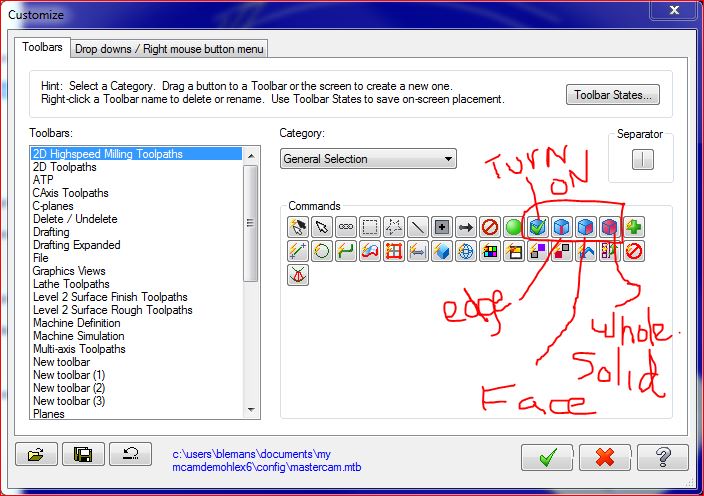
Also, you don't necessarily need to create surfaces from solids to machine this. You can choose solid faces as driving geometry. Don't know if you have this on your toolbar or not but I see you have created surfaces instead. In toolbar customize, got to category then general selection and pick these icons and drag them to your toolbar for solids selecting options......see pic
-
 1
1
-
-
devolve into "left" vs. "right" mentality.
pfffft.......like that ever happens :roll eyes:


-
I like mixing my lemonade 50/50 with 7UP,...
i like a splash of vodka with it.......just for color

Can 0i-mc Fanuc read bit locker drive encryption?
in Industrial Forum
Posted
Before I make the call to Fanuc, I thought I would ask here.
Our company has made it so we must encrypt all external devices on all computers. Is there a way to format at password protected card on a fanuc controller so it can read encrypted cards? When I password encrypt my card, controller gives me alarm 1010 and won't read card. I reformatted back to FATand that allows controller to see it with no alarms, but that obviously doesn't help me. The card worked fine before encrypting this morning.
Can't find anything on 1010 alarm so I assume that's what is going on.