


steveo25
-
Posts
139 -
Joined
-
Last visited
Content Type
Profiles
Forums
Downloads
Store
eMastercam Wiki
Blogs
Gallery
Events
Posts posted by steveo25
-
-
I think I found the bad spline you were speaking of. I blended it with blended spline. How did you create the points? and how did you get it to sync by point? i dont see that option. Were you using the old or the new swarf? Thank you for your help!
-
I am having a hard time getting a smooth 5 axis swarf cut around the profile in the attached file. Everything looks pretty good except when the cutter comes around the end opposite of the origin it wants to tilt over further than I would like. I am looking for a nice smooth toolpath. Does anyone have any suggestions? Thank you
-
Yea reko the surfaces came in missing when i imported it. Must have been a dirty file. I would need to take the time to clean it up which I am lacking at the moment
-
Thanks for the replies! Now I am thinking this part is better suited for our lathe shop on the mill turn. I was more or less curious to see if it was an easy task on the indexer but it sounds like it may not be.
I do things like this all of the time on the 4th axis... Mastercam handles it nicely. I would have put some toolpaths on your file, but the it came in with missing surfaces... if you want to send me a good file, I'd be glad to show you how I'd approach it. I really don't think you need to make it a simultaneous/true 4th axis motion part, just 3+1 IMO.
Orient the part with one of the pockets facing up symmetrical in the Z-axis... rough the pocket, finish the pocket, transform/rotate all of your paths around the left plane 7 times... done.
I see what you are saying here. Wouldnt you need to do a 3d contour or something to hit that little radius all the way around the bottom? And wouldnt you need to use a ball endmill? Thanks for the advice
-
So we have this part that we need to do on our haas indexer that is mounted on our fadal 3 axis vmc. i just wanted to get some ideas from you guys on how I should approach the cut outs on the part. I have done somewhat similar things on a mill turn with the c axis contour but on the milling side I have not done anything like this. the part is 6061-t651 aluminum i appreciate any input. thank you
-
I have had similar issues with this but in the X9 beta. It processed really slow when deleting geometry but it was only when the plane manager was open. It seems to be much better with the public release
-
 1
1
-
-
Take a look at your tool settings in the tool setup parameters. It appears they aren't setup for your intended use because the icon in the direction dialog box shows your tool facing on the bottom of your axis.
-
What are your settings in this area?
i have the same settings that you have there. It is working correctly now. This was the first time I have ever ran across this issue. I appreciate the help
-
And yes I do have X7, maybe it is time for an upgrade also
-
I do need to take a look at the post and see what I can do. When I came in this morning it was working properly so maybe I just needed to re start my computer.
Thanks for the advice
-
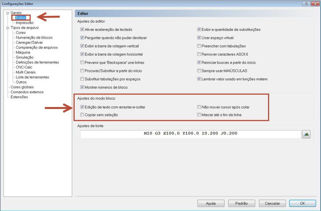
I am using Cimco edit version 5. i have a weird problem that just started happening. When I highlight code and click on it then go to drag it to a different location it deletes the highlighted code that I was trying to drag. It does this when I release the mouse button to put it where I want it. I am constantly doing this to move coolant and tool staging around. This is the first time I have ever ran into this problem. Anyone have any ideas what could be happening? Thanks in advance
-
Yea that would be great. I attached the zip2go file and the tap is the very last operation in the file. Thank you for the help
-
We have an okuma lathe here and I just use templates with manual entry. The code that I use looks like this
N600 G13(T1010 1/8-27 N.P.T TAP)
N602 G97 S477 M03 M42 P0070
N604 G0 G90 G95 X0. Z.1 T1010 M08
N606 G1 Z-.4 F.037
N608 M5
N610 G1 Z.1 F.037 M4 S239
N612 M09
N614 G0 X30.0 Z30.0
N616 M02 P1000
It is an osp7000 control and we use a floating tap holder
-
Selecting the default overlap at 10 degrees seemed to work also. Thanks for the help guys
-
Actually after messing with it a little bit I had an epiphany and thought maybe I should check my tolerance in the filter settings. My tolerance was 0.001" so i changed it to 0.0001" and that did the trick for both files. To think i have been dealing with this for that long and it was a stupid tolerance setting. attached is an X5 file
-
Here is another one. The issue on this one is on the o.d. rough tool path towards the end on operation #2
-
Thats weird. I will try posting a different part with same problem
-
here is a zip to go.
-
hmm it opens fine for me. Is there a warning sign or anything?
-
forgot to hit the attach file icon
-
I have been dealing with this issue for quite sometime now and have contacted cimtech for a resolution but havent been able to come to one. My problem is when I am doing a standard roughing toolpath in lathe (MCX 6) the tool wants to machine some of the same diameters that it just did the previous pass or passes. I have just been editing these passes out over the years but that gets pretty old. This seems to only show up depending on the part geometry and how much material needs to be taken out versus my programmed depth cuts. My question is do you guys ever deal with this problem and how do you go about fixing it or working around it? Attached is a file that I Just did and if you pay attention to the I.D. rough boring you will see it will go over diameters that have already been cut. I have also ran into this issue then closed mastercam and started back up and it worked as I wanted it to. Most of the time though it doesnt do what I want no matter how hard I try. It seems to violate my parameters for depth of cut depending on the part, features and geometry when using the roughing toolpath. Any help is greatly appreciated
Thank you for your time
-
Alright I will look them up. Thanks for the replies
-
We have a Mori NL-3000Y and we don't have a ventilation system on it to suck the coolant vapors out. I was wondering what kind people are using on similar machines out there?
Thanks
-
We will try that on this next job and see how it measures out.
Thanks
5 AXIS SWARF
in Industrial Forum
Posted
I went with the curve 5 axis toolpath. It gave me everything I was looking for. Thank you for all the help guys!