


Alan Chen
-
Posts
54 -
Joined
-
Last visited
Content Type
Profiles
Forums
Downloads
Store
eMastercam Wiki
Blogs
Gallery
Events
Posts posted by Alan Chen
-
-
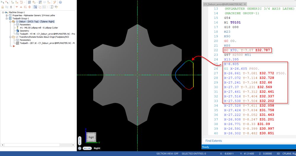
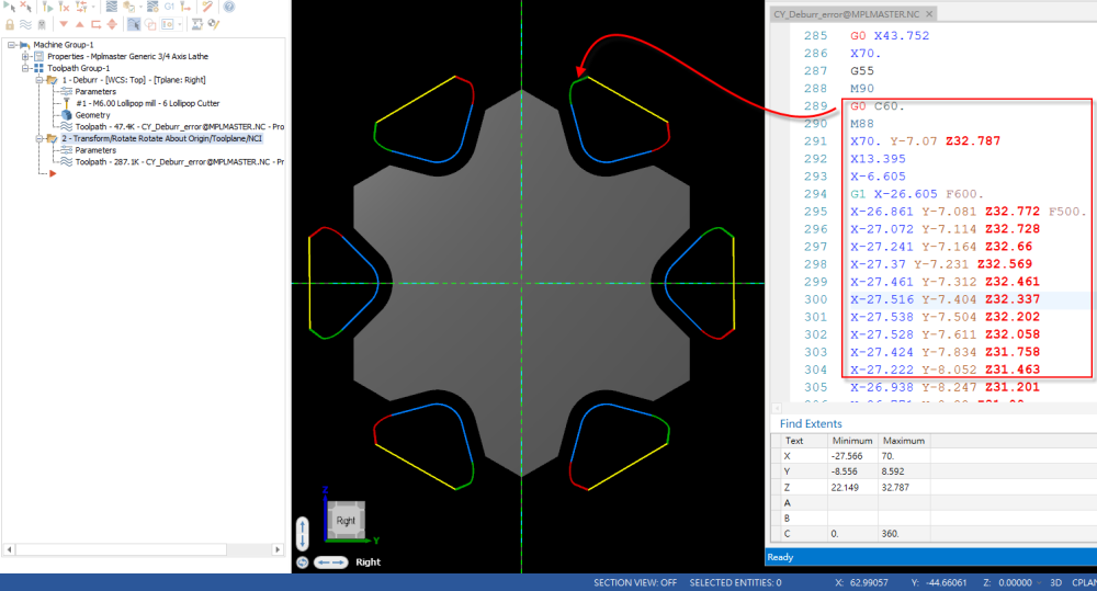
Is there anyone who encountered this situation?
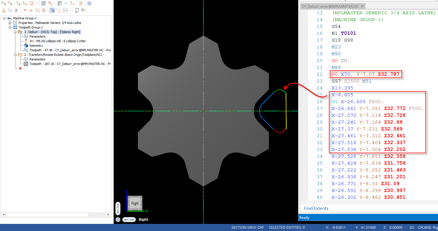
I use Lathe with Mill 5-Axis Deburr.
That NC code look like error, X value immediately changes from a positive value to a negative value.
And some X value was -6.605, then move to -26.861 ?
In this case, the X position must be positive, because cutting on righe side.And I use deburr machine one place and then use the C-axis to generate other paths.
The nc code all wrong the same with first.Thank for your help.
-
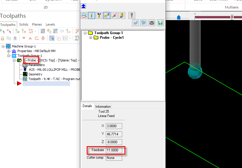
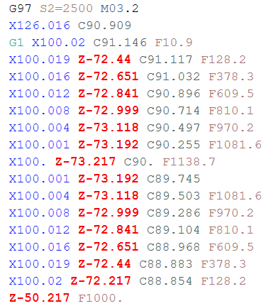
Dose anyone can teach me how can modify Mastercam Probe Backplot Feedrate ?
Thanks...
-
On 9/12/2019 at 9:25 PM, Alex Dales said:
Hi Alan,
We discussed this via email, but if anyone else come across this issue, we discussed a solution to use cuttype = 0 to indicate lathe toolpaths and set dia_mult to 2 for those, and 1 for all others.
Cheers,
Alex
Hi Alex,
Thanks.
But I don't receive your mail, can you send to me again.Now I try to modify
dia_mult : 1 #Multiplier for output on X axis (Neg. switches sign of X)
x_mult1 : 2 #X axis for cuttype 1 #Turning
And set pfxout pxout
if cuttype = one, x_mult = x_mult1 #Turning #(Alan A)
if abs(cuttype) = two, x_mult = x_mult2 #Right/Left Face cut #(Alan A)
if abs(cuttype) = three, x_mult = x_mult3 #Cross cut #(Alan A)
if cuttype = four, x_mult = x_mult4 #Y axis substitution #(Alan A)
if cuttype = five, x_mult = x_mult5 #Multisurf Rotary
But some parameter still error with drill retract. -
Can you help me that I want to output X value in C-Axis toolpath with radius.
Before was G0 X12. Y16. Z45.6 , but I want to output G0 X6. Y16. Z45.6
I know that dia_mult : 2 #Multiplier for output on X axis (Neg. switches sign of X)
But it will change all of X include Lathe toolpath.
I want to only with Mill toolpath.Thank you very much !
-
Yes..
Axis-Substitution was current, if that machine don't with Y-Axis.
-
On 10/6/2018 at 2:01 AM, Alex Dales said:
This is am issue that has always bothered me. If you look at the backplot you will see that even though C-axis is selected, the tool is not always pointing to center, which indicates a Y-axis move. This means that processing this toolpath as a Y-axis move will result in machine motions different from the backplot.
If you are using a ballend, the angle deviation is not important, but by default, we have set the logic to match the backplot.
But don't worry, the Logic you are looking for is still in your post. It is just commented out. It is a quick change to make in the postblock pxyzcout2 as outlined below. You just need to uncomment the C-axis preference and comment out the Y-axis preference math.
Original code:
pxyzcout2 #Polar conversion, Cross cut, Right/Left Face cut
#Drill polar is toolplane drilling toward center
#if not a coincident axis (Face cut)
if (y_axis | (opcode$ = three & abs(cuttype) <> two)), pxyzcout0
else,
[
cfeed_x = sqrt(xa^2 + ya^2)
cfeed_y = zero
cfeed_z = za
#if opcode$ = three & abs(cuttype) = three, csav = c$
#else, csav = atan2(ya, xa) + c$
if opcode$ = three & abs(cuttype) = three, csav = c$
else,
[
if abs(cuttype) = 2,
[
if fmtrnd(xa) = fmtrnd(prv_xa) & fmtrnd(ya) = fmtrnd(prv_ya), csav = prv_csav
else, csav = atan2(ya, xa) + c$ #on the face you need to add c$ in case of twisted face plane
]
else,
[
csav = c$ #cross cutting with rotary turned on (NOT AXIS SUB!)
cfeed_y = ya #C only indexes to plane and then Y motion
cfeed_x = xa
]
]
pax_shift
ipr_type = one
if not(millcc & abs(cuttype) = two),
[
if fmtrnd(xa) = zero & fmtrnd(ya) = zero & opcode$ <> three,
pnt_at_zero = one
]
]New Code
pxyzcout2 #Polar conversion, Cross cut, Right/Left Face cut
#Drill polar is toolplane drilling toward center
#if not a coincident axis (Face cut)
if (y_axis | (opcode$ = three & abs(cuttype) <> two)), pxyzcout0
else,
[
cfeed_x = sqrt(xa^2 + ya^2)
cfeed_y = zero
cfeed_z = za
if opcode$ = three & abs(cuttype) = three, csav = c$
else, csav = atan2(ya, xa) + c$
#if opcode$ = three & abs(cuttype) = three, csav = c$
#else,
# [
# if abs(cuttype) = 2,
# [
# if fmtrnd(xa) = fmtrnd(prv_xa) & fmtrnd(ya) = fmtrnd(prv_ya), csav = prv_csav
# else, csav = atan2(ya, xa) + c$ #on the face you need to add c$ in case of twisted face plane
# ]
# else,
# [
# csav = c$ #cross cutting with rotary turned on (NOT AXIS SUB!)
# cfeed_y = ya #C only indexes to plane and then Y motion
# cfeed_x = xa
# ]
# ]
pax_shift
ipr_type = one
if not(millcc & abs(cuttype) = two),
[
if fmtrnd(xa) = zero & fmtrnd(ya) = zero & opcode$ <> three,
pnt_at_zero = one
]
]Thanks for Alex...
That solves my Obsession.Because the post for student use.
Some machine don't have Y-Axis, and someone will forget to use other function to create toolpath.
So, I need to let them output X&C code.
I understand that toolpath not correct, it's need Y-Axis to machining...Thank you very much....
-
 1
1
-
-
On 10/6/2018 at 2:14 AM, Alex Dales said:
Use Parameter number 10519 in pparameter$ to read in the value to a variable
Thanks for Alex.
I found form MP-Documents..
-
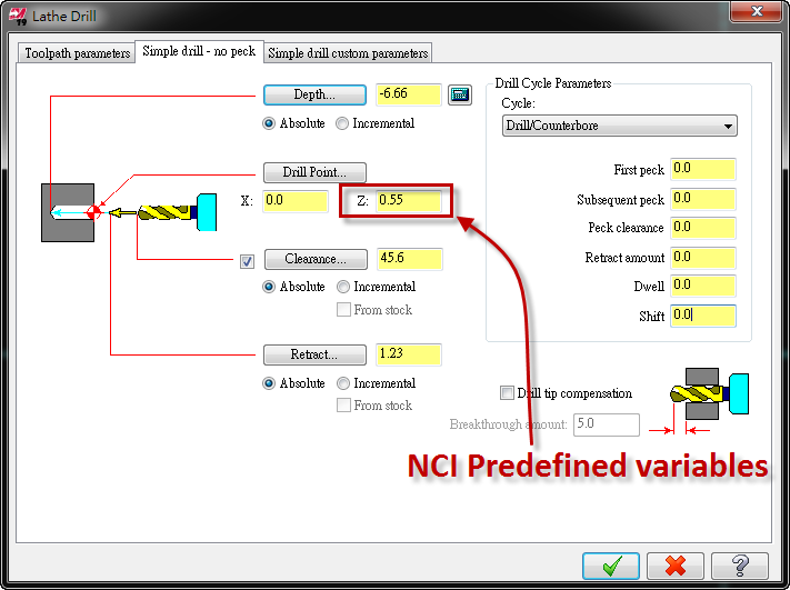
Please help me that "Drill Point" NCI variables, because I need the value to output.
Thanks...
-
Please help me to this problem.
About Test.mcam , we create C-Cross Toolpath and select output C-Axis.
This part need use Y-Axis, but machine only has C-Axis.
So we need output toolpath output X&C..In MPLmaster.pst, that only can output Y-Axis motion, but when we use MPLFAN.pst & Generic Fanuc 4X MT_Lathe.pst that can output X&C motion.
MPLmaster.NC:output Y-Axis motion
MPFan.NC:output X-Axis & C-Axis motion
Fanuc 4X MT_Lathe.NC:output X-Axis & C-Axis motion
Thank for help...Mastercam file and NC files
Test.zipMachine and post files
Shared Mcam2018.zip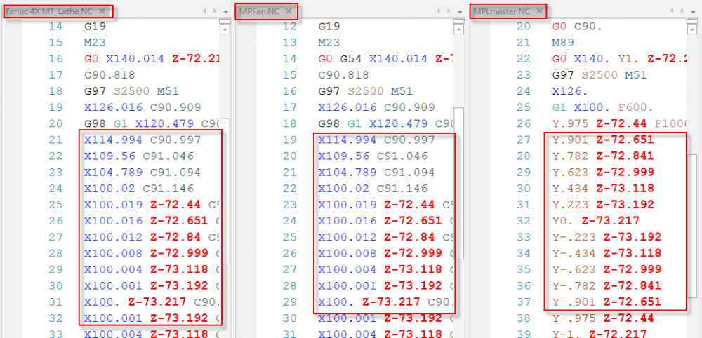
-
Unfortunately, that "0.0 degree position" option isn't "hooked up" to anything inside the post.
Mastercam post processors are setup with the "MP.DLL" post engine (the dynamic linked library), setup to do most of the "heavy lifting" for you. What this means is the MP engine is setup to process and calculate things a certain way, based on "conventions" that were setup a long time ago.
So, if you want to follow the "programming conventions" that Mastercam setup to work with the "default" values in the post, then everything is "easy".
What you want to do; which is use a "non-standard" way of setting up Mastercam and the Post, to drive output for your machine.
The biggest "convention" that you have to either work with, or overcome, is the way that Mastercam's MP.DLL uses "Planes" to automatically calculate Rotary output angles. There are two basic formats:
Top/Top - Top WCS, Top T/C Planes, mean that you can use X or Y as the Rotary axis. Which one you use is "up to you", but you must be consistent about how you create your planes. So if you are rotating on the X Axis, all of your T/C Planes must have the X+ direction remain fixed, and each Tool Plane must be a rotation of the Gnomon (XYZ Triad), that is rotated about the X+ axis.
The same is true if you are rotating about "Y". All planes must be a rotation where the Y+ direction is "fixed" and all the planes have the Y direction constant.
Those are the two options for "VMC" or Vertical programming.
For a Horizontal machine, MP.DLL expects you to use Top/Front for your programming. That is the "Top - WCS", and the "Front" T/C Plane.
All rotations for a Horizontal machine must use the "Front" plane as "B0.0", and the plane must be rotated about the "Front Y+ Axis". As long as all your planes are "Front" based, and the Y Axis remains fixed, you are good to go.
Now, you've got a situation with your machine where the "conventions" of the machine, where the Rotary B0.0 face does not match the Front Plane in Mastercam.
So, you are in a bit of a pickle. Now fortunately, I am pretty well versed in the Rotary Processing aspects of the MP.DLL engine.
The main variable inside the MP-based post processors that controls "Rotary Processing" is 'rotaxtyp$'.
'rotaxtyp$' is the secret. Based on the value of this variable, MP.DLL can be configured to process many different types of rotary motion. The "main" use is for controlling 4 Axis configuration, but you can also setup 5X or Mill-Turn plane processing, by changing the value of 'rotaxtyp$'.
For the variable, there are several different settings that tell MP how to process planes, and which "plane" is the "0.0 Reference Plane".
The values are as follows:
-3 = Single Axis Rotation. Sets the reference tool plane to the Right Side Plane view for 'c$' angle equal to 0. Rotation is about the Z axis of the WCS. 'c$' is returned in the range of 0-360 degrees, CCW positive.
-2 = Single Axis Rotation. Sets the reference tool plane to the Front Plane view for 'c$' angle equal to 0. Rotation is about the Z axis of the WCS. 'c$' is returned in the range of 0-360 degrees, CCW positive.
-1 = Single Axis Rotation. Sets the reference tool plane to the Top Plane view for 'c$' angle equal to 0. Rotation is about the X or Y axis of the WCS. 'c$' is returned in the range of 0-360 degrees, CW positive about X, CCW positive about Y.
0 = Single Axis Rotation. Sets the reference tool plane matrix to the First Operation View in the NCI file for 'c$' angle equal to 0. Rotation is about the X, Y, or Z axis of the WCS. 'c$' is returned in the range of 0-360 degrees, CW positive about X, CCW positive about Y or Z.
1 = Single Axis Rotation. Sets the reference tool plane to the Top Plane view for 'c$' angle equal to 0. Rotation is about the X or Y axis of the WCS. 'c$' is returned in the range of 0-360 degrees, CW positive about X, CCW positive about Y. This is identical to the '-1' setting.
2 = 5 Axis Rotation. Intended for rotary motion in Tables. Tool Plane Tool Paths: must be supported in the post customization file by calls to the postblock 'pmx0$' pm every motion post block call. The post writer is responsible for all rotary calculations and position mapping.
3 = Mill/Turn Applications. Resolves 'a$' and 'c$' angles when rotated about the X Axis.
Cross: the base view must be "BACK (view 3)" for 'c$' angle equal to zero. 'c$' is returned in the range 0-360, CCW positive. 'a$' os returned as '0.0'.
Face: the base view must be view "RIGHT SIDE (view 5)" for 'c$' angle equal to zero. 'c$' is returned in the range 0-360 degrees, CCW positive. 'a$' is returned as '90'.
Back Face: the base view must be "Left Side (view 6) for c$ angle equal to zero. 'c$' is returned in the range 0-360 degrees, CCS positive. 'a$' is returned as '-90'.
4 = 5 Axis Rotation. Intended for rotary motion in the head. Tool Plane Tool Paths: must be supported in the post customization file by calls to the postblock 'pmx0$' pm every motion post block call. The post writer is responsible for all rotary calculations and position mapping.
5 = Shuts of rotation. No mapping or calculations are performed for Tool Plane Positioning. Post writer is responsible for all angle calculations, although post may not call post blocks in the "expected" order, so care is needed in testing for proper output.
6 or Greater = Allows rotary support in the post customization file by making the call to 'pmx0$' on every motion postblock call from 'prapid$' to 'pg32e$'. (See database order (mill/lathe) in Volume 3). Calls for the output postblocks are limited to those normally called with 2D and 3D contour motion. The post writer is responsible for all rotary calculations and position mapping. (Note: 'rotaxtyp$' should be set to a large value (example: 9999) to allow future expansion of this variable by CNC Software.)
I learn more....
Thank you very much...
-
Thanks...
I try to modify the pxyzcout with coffset
coffset : 90
pxyzcout #Map coordinatesif rot_on_x,[if cuttype = zero, pxyzcout0 #Toolplane Positioningif cuttype = one, pxyzcout1 #Axis Substitutionif cuttype = two, pxyzcout2 #Polar Conversionif cuttype = three, pxyzcout3 #Simulatneous 4 axis (Multi-axis)if rot_cw_pos & vmc, csav = -csavif not(rot_cw_pos) & not(vmc), csav = -csavcsav = csav + coffset -
I try to modify the other line along the 0 degree position , but nc output is the same..
-
Greetings All...
I use MPMaster.pst with mpmaster_horizontal.mmd-9, that the machine 0 degree position was at left side not front.
I have select the axis that lies along the 0 degree position of the rotary axis like this picture.

But that always output C0 with front side.
What parameter that I need to modify..??
Thanks...
-
Thanks, I will try to install tomorrow..
-
To change the program number of existing operations,
we can select an operation and right-click in the Toolpath Manager.
Choose Edit selected operations, Change program number.
But it's too hard, because I want to change every operations..
Like version 9, we can set program number in parameter page..
How can easy change program number..??
Thanks...
I think I want to use VB Script..
But can't find the parameter...
-
Does anyone know whay's "5-Axis simulate software" is the best...??
If I use Mastercam to gernarate 5-Axis NC file.
How can I simulate it only use nc file..
-
Thanks...
I will try...
-
Does anyone call tell me
What is this code in MplMaster.pst..
sm88 M88 #Brake/Mid-Clamp On
Thanks...
From here ..
-
Günther Massimo..
Sorry...Can we translate to local language...??
SetupX+...
-
can I see that example also?
-
-
You can check this setupsheet...
But It's chinese version...
http://www.mcam.com.tw/images/setupsheet.jpg
I can modify to English version...
But need time and not free...
-
I modify mill.set , I try to set the toll's feedrate.
first operation is 300. ; second is 500.
But the fr_pos$ always output 300.
Can anyone tell me how to add parameter in fprmtbl
fprmtbl 1 3 #2D Contour
10010 stock #XY stock to leave
10068 zstock #Z stock to leave
10031 plunge # Plunge rate
????? ?????? # Feed rate
Thanks...!!
-
I have modify the post finish...
Can you test for me...??
Thanks..


CY_Deburr_error@MPLMASTER
in Post Processor Development Forum
Posted
Yes.
I use save the deburr operation backplot as geometry, then output the NC code.
But I think the MPLmaster maybe will be update with deburr operation.