


Mariana Lendel In-House Solutions
-
Posts
73 -
Joined
-
Last visited
Content Type
Profiles
Forums
Downloads
Store
eMastercam Wiki
Blogs
Gallery
Events
Posts posted by Mariana Lendel In-House Solutions
-
-
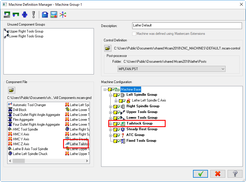
You have to make sure that in the Machine def, Machine configuration window you have the Tailstock Group as shown. If not just drag it from the Component area.
-
What Mastercam version are you using. Usually it gives you the option in the chaining dialog box and also in the Toolpath Type.
I just notice that you are using Dynamic Contour. You have to use Dynamic Mill to have these options available.
-
I usually define the planes by rotating the top plane, but I guess the back plane works too.
-
The tutorial does not cover information related to misc values switches.
These are usually used by the post processor for your specific machine.
-
Another ATP tutorial that shows how to use a cut list generated KCD software is going to be available soon.
-
 2
2
-
-
Just to clarify, this tutorial covers ATP using Mastercam configuration and the cut list is based on an excel spread sheet.
-
Here it is.
.gif ":)")
-
The second issue. I am guessing, in the OptiRough, you are using the Stock dialog box and enabled Rest material.
I will go with Compute remaining stock from One other operation and select the OptiRough with the 1/2" tool.
Adjustments to remaining stock can be set to Ignore small cusps and you can leave the distance to 0 or add a small amount.
If you want the tool to retract and machine the corners, in the Cut parameters you should set the Motion > Gap size retract to.
Enable When exceeding a distance or/and Avoiding a boundary and set the distance as needed based on your model. Otherwise Mastercam keeps the tool down.
I would set Linking to Full Vertical Retract and the Linear entry/exit to a bigger value. You will get a lot of rapid moves unfortunately.
-
The best way is to bring the model in Mastercam in imperial and then switch it to metric and program everything in metric.
Another option is to let a customize post processor to make the conversion for you.
You will be charged for that post processor and there could potential issues such as the arc output with I&J values. This is due to the tolerance differences between imperial and metric (0.001 versus 0.02).
To sum it up, convert the part to metric and set Mastercam system configuration to metric, select the metric machine. While programming use the metric tools or, in 2018, select the inch library and pick the inch tools. Mastercam will do the tool conversion automatically in 2018!
-
If the island is at the same height with the top of the part you only need 2d geometry. I usually set Z zero at the top of the part.
In the Dynamic Mill toolpath, select as Machining region the pocket chain and as Avoidance region the island chain. (2018 - I do not know what version of Mastercam are you using)
In the Linking give the depth of the pocket -1 (If the pocket is 1" deep)
If the island top is below the top of the part you need to create the geometry used in the toolpath at the proper z depth.
In my next example, z zero is at the top of the part; the pocket depth is at -1" and the top of the island is at - .25 (both measured from Z zero).
Create the 2D geometry at z zero.
Use Translate command to move the chains at the proper Z depth:
Select the pocket geometry (Hold down the shift key and select one of the pocket entities)
In the panel, enable Move and enter in the z field -1.
Repeat the step for the island chain and enter Z-.25.
In the Dynamic Mill toolpath, select as Machining region the pocket chain and as Avoidance region the island chain. (2018 - I do not know what version of Mastercam are you using)
If you want to face the island, in the Depth Cuts:
enable Use Island depths
enable Island facing and give an Overlap 25% or more.
In the Linking give the Depth incremental and 0.0.

-
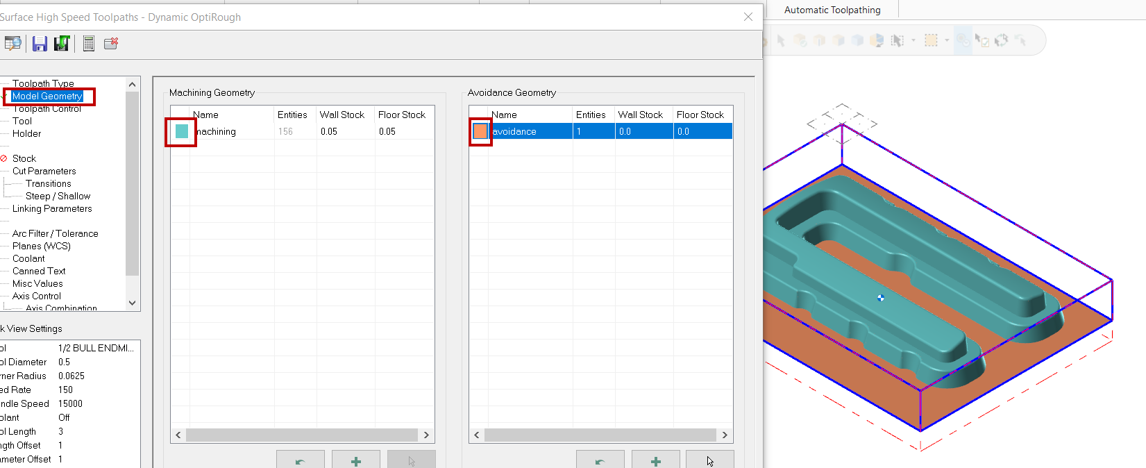
Regarding "DOES ANY BODY KNOWS IN 2018 WHERE THEY HAVE DISPLAY OPTIONS TO HIGHLIGHT GEOMETRY OF THE TOOL PATH. IT IS AVAILABLE IN 2017 BUT SOMEHOW THINK THEY HAVE CHANGED IT IN 2018. "
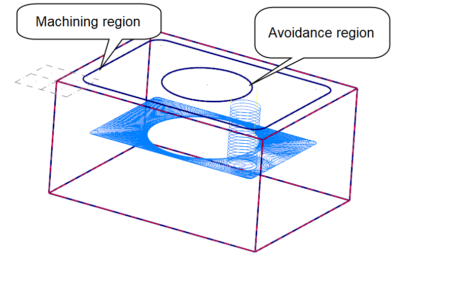
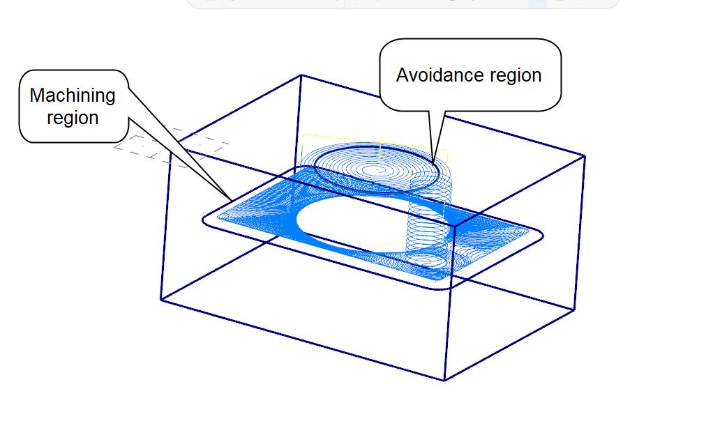
I am not sure if this was intended to replace the option, but in the Model Geometry, you can now set the color for the Machining geometry and the Avoidance geometry.
If you hide the dialog box, (or just drag it away in my case) you will see the colors on the part.
To change the colors double click on them and the Colors dialog box will appear.
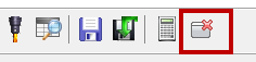
To hide the dialog box, select the Hide dialog icon located at the upper left corner.

-
1
-
-
Yes, you can use Quickpart with router9.
In desktop right-click on Quickpart icon, choose Properties, and change C:Mcam9MILL9.EXE qp3dv9.dll qp3dv91.cfg to C:Mcam9Router9.EXE qp3dv9.dll qp3dv91.cfg
-
Create the island geometry at the final z depth, set the pocket type to island facing and check the box in front of Use island depths in the Depth cuts dialog box.
Mariana
-
Our training is broken in two separate parts, design and toolpaths. I do have 31 drawings for design and I provide a guidline for each day of training in which I mentioned the drawings that have to be completed. The faster trainee could just follow the guidelines. I check his drawings as they are finished.
For the toolpaths you can use the drawings and some of the samples drawings that come with the software.
You can also give to the slower trainees the demo CD and give them homework, for practice.
Mariana Lendel
-
I use a set of multiple choice questions in a game format that allows me to review the material. For the final test I give them a part drawing and a list of information regarding the toolpaths to machine it.
-
You can set the outside ellipse as a boundary. Prompt for the tool center boundary in the parallel toolpath, and select the ellipse after you exit the parameter dialog boxes. Keep in mind that the system considers this to be the tool center boundary. Hope it helps.
-
About 4 years ago, when I first had to deal with Imperial system I was very fustrated. I still have to "think" in metric to actualy "see" the dimension, but I guess you like what you are used to better. It will be nice to have one measurement system, but till than...

-
Are you using lead in/out? You need a linear movement at the beginning to compensate the radius of the tool.
-
Both have the tool oriented parallel to the walls. Roldie allows simultaneous four axis movements while swarf can generate 4 or 5 axis movements.
For Swarf you can specify a tip control, you can define the walls using surfaces or two chains, plus in parameters you can set an entry /exit.
Roldie can be used to machine sharp inside corners; the tool will automatically ramp up inside the sharp corners.
Hope it helps.
-
If you are changing the diameter of the tool and you used cutter compensation in computer, you have to change the tool in Mastercam and Regen path. If you used cutter compensation in control then just change the diameter offset at the machine.
For the tool height you change the height offset at the machine.
[This message has been edited by Mana (edited 06-13-2001).]
-
Parametric splines require more memory in the database. Mastercam defaults are for NURBS.
-
Sorry that our tutorials don't cover all the information that you would like to get from a software manual. They are just application tutorials in which we are trying to give some examples of how to generate toolpaths in a given situation. They were not meant to teach you the software inside and out and I am aware that a lot of information like the "why's" are not covered in them. They were meant for beginners to become familiar with the sofware and not to replace the training.
Thank you for you sugestions. We will take them in consideration when improving the tutorials.
-
Go in Screen, Statistics and see what it shows you in the promp area. How many lines arcs etc you have on the screen to figure out if you have surfaces, solids or just lines and arcs.
-
If you are refering to Mill Training Tutorials, the surface type that you have to use on exercise 1 of tutorial 15 is coons.(No Automatic coons chaining, using the point at the bottom of the "spoon" as the fourth side; 4 patches in the along direction 1 patch in the across). It's kind of similar with the step-by-step tutorial.
Defining Tailstock
in Industrial Forum
Posted
Then, make sure that you set it up in the Stock setup as needed.
Use the Lathe tailstock toolpath. If you need any special code such as dwell time you need to make or ask for changes in the post.