


tony1001
-
Posts
33 -
Joined
-
Last visited
-
Days Won
1
Content Type
Profiles
Forums
Downloads
Store
eMastercam Wiki
Blogs
Gallery
Events
Posts posted by tony1001
-
-
I have a piece of heat treated Elmax (similar to 440C) that needs an existing 1/4-20 screw hole to go deeper. It was originally tapped in its soft state, but a modification has been made so now the hole needs to go .250 deeper. It is too hard to use a carbide tap on it, so I would like to thread mill it instead. I have thread milled stuff like this before, but the problem I'm having is how to pick up the same lead on the thread that is already there. Is this possible?
-
Thank you guys for the help. I did try some of your suggestions and I got a toolpath that I was happy with that ran good in the machine.

-
 4
4
-
-
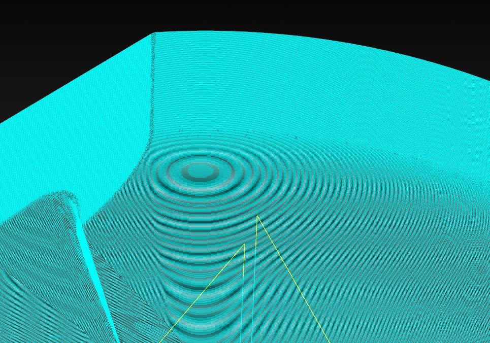
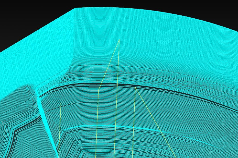
I have some surfaces that I am working with and I can't get a good cut pattern. I attached a file of what I have done with the Unified toolpath. If use Guide, I get weird dips along the edges of the cut. With Morph, it cuts through and behind the surfaces. I thought checking the box "round corners" would help and tried different values, but then it looked even worse. I have been messing with this for a while today, but could use some help with it.
Thanks,
-
I found what I was doing wrong. In the Transform toolpath, under Method I had it set for Tool Plane. Once I changed it to Coordinate, the machine simply moved over to the next location and started cutting without have to retract the Z all the way to reset the 10° plane.
-
I am using a Transform/ Translate Rectangular on 10 degrees in a 5 axis mill. It will run the first location fine, but when it goes to the next location it needs to unlock the B and C axes (M13 and M11) resets itself to the angle, then locks the B and C again (M12 and M10). I am needing to manually add the codes to the file in order to unlock and lock. Is there something that I am missing in the parameters or maybe in the control or machine definitions that will add the M codes to the posted file? Below is a section of the code. Once I manually added the M13 M11 and M12 M10, the file ran fine in the machine.
G54 G90
M13 M11
G00 B13.6885 C4.6796
G68.2 X.95 Y0. Z0. I90. J10. K0.
G53.1
M12 M10
X.30127 Y1.46681
G43 H1 Z1.
Z.1
G01 Z-.4 -
Thank you Aaron. I have been trying what you suggested. I still don't have it just right yet, but doing a morph from the top edge to the floor curve got me a lot closer to what I was looking for.
-
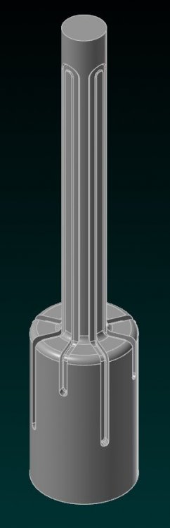
I have been asked to hard mill a thread on a pin and I can't quite seem to get what I am looking for. I attached a file with a section of the part that I am working with and have tried a couple of toolpaths on it. I'm not sure if I'm on the right track with it, or if there is some other way to go about it. I would appreciate any advice to get pointed in the right direction.
Thanks
-
Great, thank you for taking the time to look at that!
-
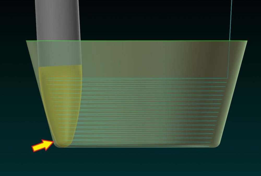
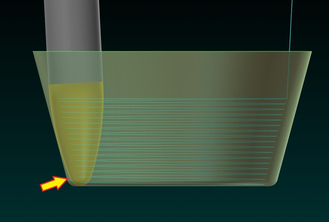
I was experimenting with an oval form cutter and can't seem to figure something out. I used a parallel toolpath to do the 10° taper and used the radius and floor surface as avoidance geometries in the collision control tab. For the tool axis control, I used surface with tilt, follow surface iso direction, and a tilt angle at side of cutting direction set at -78° (+78° made the cutter come from underneath the part). I get that it is locked at that tilt angle, but what type of tilt control do I need to do to make this cutter reach into the corner where there is still a gap? Can it be done in one toolpath or do I need to make it a separate tool path with a different tilt control?
Thanks,
-
Thanks guys, all of this helps!
-
2
-
-
16 minutes ago, crazy^millman said:
Same tool for the smaller diameter. Going to be fighting chatter on that small diameter that long, but with that machine you not given much options. I would make my own working holding and then manually rotate the part to each place I need to cut those grooves so I can support it top and bottom, not just from the bottom you would be limited to. Yes I have made my own fixtures for index parts on 5 Axis machines.
Then need to use Parallel to curve and work on those transitions.
Ok, I will try parallel to curve. The good thing is that they are mounted on 3R pallets so once I figure out how to cut one channel, I can Transform/Rotate to do the others.
Thanks for the advice.
-
I did what you were saying about using a bull endmill for the channels on the bigger diameter. Here is the Mastercam 2022 file. It will be for a Makino D200Z, which is a table/table machine.
Thanks,
-
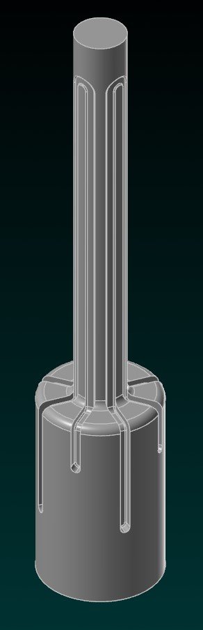
I have been trying different tool paths to do the channels on this part and I can't seem to come up with anything I like for it. I would like to know how some of you guys would go about doing this. The dimensions aren't critical on it and I know vibration will be an issue near the end of it, but at this point more than anything I would like to know what toolpath would work best for it. I took some details off of the part and left a parasolid with only the channels I would like to know about. What do you guys think?
Thanks
-
I get the same things as some of you guys when trying to create fillets, but one more thing that it does to me is that it turns on auto highlight for solids until I close out of Mastercam and then reopen it. It does it without fail every time I create a fillet.
-
I just started using 2021 this week and noticed that every time I use Alt+E to keep geometry on the screen for a toolpath (just a simple 2D contour), when I go to chain it, it will keep wanting to select entities that are supposed to be hidden. The entities aren't showing on the screen, but the toolpath chain arrow will be off in space somewhere as if it were chaining invisible geometry. Is anyone else having this issue?
-
I haven't experimented much with the high speed toolpaths, usually I stick with the the old standard surface toolpaths. In this case though, I'd like to use Equal Scallop since it has options for tilting the tool and holder away from the the walls as it gets further down into the part. With Surface Finish Constant Scallop I get a toolpath that looks pretty uniform. With Equal Scallop I get a toolpath that doesn't look as clean and has wider spacing in some areas. What can I look for in the parameters to make Equal Scallop look a little cleaner?
Thanks
-
Got it, thanks!
-
Ok, thanks. I will see if I can get my supervisor to download it since I am unable to.
-
1
-
-
On 4/21/2019 at 7:04 PM, Colin Gilchrist said:
BTA,
Have you downloaded a copy of the Moduleworks Help File yet? There is a link on the main forum page to download a copy of it. This help file has a ton of information that is specific to each cut strategy.
Could you tell me where the link is for this documentation? I looked on the main forum page but I didn't see it.
Thanks
-
Wireframe tool works now when I backplot my toolpaths. My computer out here in the shop needs administrator privileges in order to get into the advanced configuration for both Mastercam 2017 and 2018, for some reason. I asked our IT guy to change it to disable GAF, which made no difference at first, but then he did something on his end to allow permission to the advanced configuration and now it has the options for plain, fluted, or shaded tools. It still is a little weird though using the plain tool because it will show the tool, but then it will disappear at each endpoint when backplotting.
-
Thanks for all of the replies. I'll just live with it the way it is for now.
-
Hmm... that's weird. That is what my settings are at, but still no option for plain tool.
-
Yes, and restarted my computer.
-
I disabled the GAF, but for some reason I still don't have the option of plain tool in the backplot- it still only shows shaded tool.
Is it possible to pick up an existing thread?
in Industrial Forum
Posted
Thanks for all of the responses. It has been decided after all that we are going to make an electrode to clear the material below the existing thread.