


badbascom
-
Posts
5 -
Joined
-
Last visited
Content Type
Profiles
Forums
Downloads
Store
eMastercam Wiki
Blogs
Gallery
Events
Posts posted by badbascom
-
-
The BEST method when using Z- length offsets (which I detest in the first place but that's a story for another day) is to get a tool length setter (see below) and put that tool setter on the table or some other location that won't change.
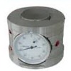
Then in your work offset you have the distance from the setter to your part Z zero. This is superior to the paper/shim method because once you remove material from the initial setting position, you can;t ever go back and reset something.
If that's not a possibility, I prefer a gage pin over paper or shims.
JM2C
Thanks, please give me the other story, pretend its tomorrow haha. Are Z-length offsets not the best way. I only do it the way I do because I dont know any better.
-
on our fadals we use the utility cycle or the SL, command to touch off the tools on -Z- to wherever -Z0- is in the program.
this puts the tool length into the geomety page not the fixture offset.
our fixture -Z- values are only to set the differance in hieght between the first fixture and the second fixture etc. we also use this value to do a globle adjustment
of all the tools that run on that fixture.
Ken,
Thanks, do you zero tools with paper shim or some better method?
-
So on our Fadal VMC we find X0Y0 with either a edge finder that sends a signal to the controller or locate a hole with an indicator and assign to a fixture offset #, we leave Z alone and zero each tool on the applicable fixture using a piece of paper. The one time I zeroed Z on the fixture offset I almost sent the tool thru the machine table.
So Im assuming my method is very antiquated, what is the best practice and technology I could add (probes, etc) to set-up fixtures.
-
I am configuring mastercam to program a Huffman 5-axis grinder. I have relented and hired a third party to develop the post but I am frustrated that I cannot figure out some of the simple problems. This grinder is similar to an HMC except that the tool points in the -Y axis direction, Table moves in standard X & Y with a C & A rotary, spindle is horizontal but moves in the Z, up & down. I have defined the tool orientation as RIGHT plane in machine configuration. When I make a simple 2d contour cut with WCS & T/P planes in TOP, verify shows the tool to be in the Z-axis. If I make the cut with the T/Plane set to RIGHT the post attempts to rotate B axis 90 to orient the part.
Any thoughts?
PS I have tried to confirm this with simulation but I get a "Check machine configuration file" error.
Restarting a long program on a Fanuc
in Machining, Tools, Cutting & Probing
Posted
My FADAL allows starting at any cursor position, I place cursor on appropriate line and use the search moduls and restart command.