John Troutman
-
Posts
5 -
Joined
-
Last visited
John Troutman's Achievements
")
Newbie (1/14)
1
Reputation
-
I am not facing the part in the same setup, so that could very well be it. Since the material is UHMW, it's very likely it's bending in the vice I have it on. Next time I'll face the part first and reference that surface for my top datum, and then see what happens. I feel like an idiot now. EDIT: Just got out the micrometer, and there is a 0.015 deviation in thickness from max to min across the part. Depending on how the part was put in the vice, that could definitely cause this problem, as that deviation is significant compared to my chamfer dimension. I should've faced the part before setting datums.
-
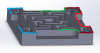
I don't know if that corner in particular is a problem, and I definitely see your point... I forgot to add a round there. However, that's not the whole issue; My issue is, better explained: Put the workpiece in a vice on the mill table as usual. I've attached a screenshot where I've colored what's happening. The red edges get a nice chamfer, it kind of tapers off over the green portion, and the blue part gets no chamfer at all. The same general trend happens with the inside contours. I know this particular part is trivial, but I want to figure this out for use on some important parts I need to make. I ran this part first on a converted CNC benchtop mill, and had the issue I spoke off. Then, I moved across the shop and re-tried it on a Haas VMC and had the same issue, so I'm having trouble writing this off to hardware errors.
-
Okay, I've attached the MC4 file. This part is 2.75 inches square. When looking at the part as one would view it from the front of the mill, the edges towards the left side are more chamfered than the ones on the right side. The slots in the part are 1/8" wide, milled with a 3/32" cutter, and I'm using a 1/4" chamfermill. Maybe I need a smaller chamfer tool? 275X275 SQUARE MAZE.MCX
-
Yes, the chamfers are big in the same places on both machines. To test the sort of thing you're implying, I've also tried the chamfer on a different part, and the same result happens, big chamfers in some spots and small in others.
-
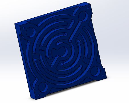
I have a problem that when I set up Mastercam to chamfer edges, often it chamfers certain edges more than others. For instance, the other day I made a little ball maze thing and wanted to use a chamfermill to deburr it. So, I selected the appropriate edges as a 2D contour and set up a 2D chamfer operation. (I attached a picture of the part.) Everything looked okay in the verify and backplot, but once I ran the program, it chamfered certain edges nearly 10 thou more than others. I tried re-creating the toolpath and running it on a different milling machine, but the same thing happened again (different brand of machine and controller). I'm not certain why this happens. I'm wondering if anyone here has had this problem and might know of a solution?