


yestwp
-
Posts
22 -
Joined
-
Last visited
Content Type
Profiles
Forums
Downloads
Store
eMastercam Wiki
Blogs
Gallery
Events
Posts posted by yestwp
-
-
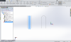
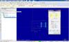
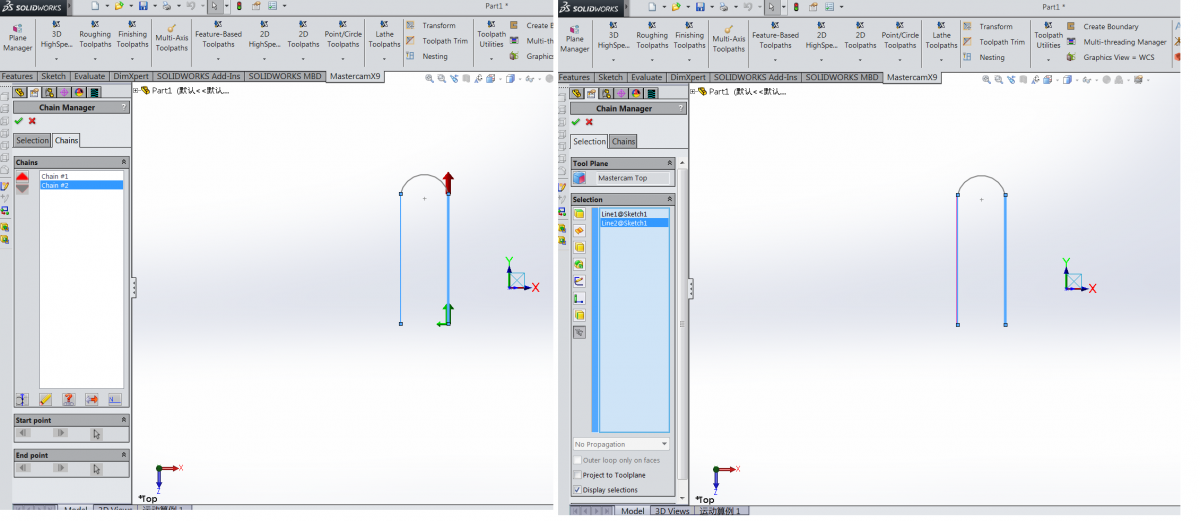
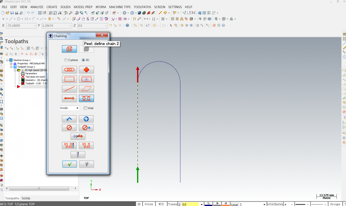
"...first of all, i select the left line. mcxFORsw give me a chain1.
and then i select the right line. it give me a chain2. it seems everything are just fine.
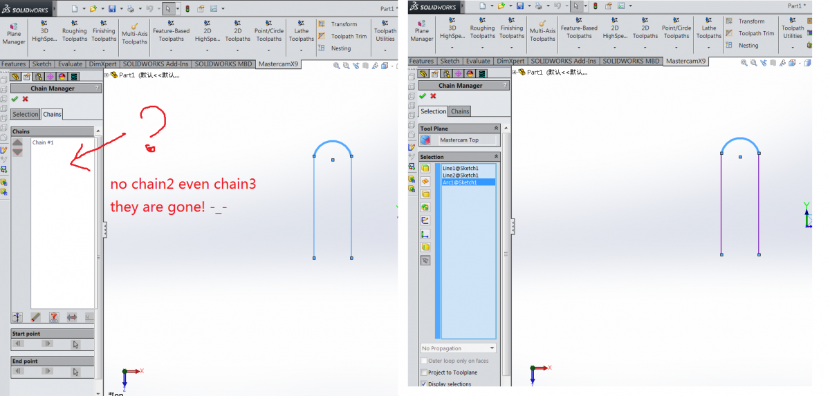
but after i select the arc. something happen...."
Once you've selected all three (the 2 lines and the arc connecting them) MCforSW sees that all 3 selections form a chain, so now it combines them into one.
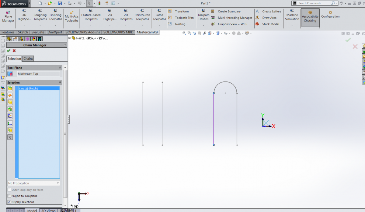
I guess you could break the arc somewhere and then put a small gap at the break - then the two sides would not connect to each other.
But the chaining in MCforSW is different enough that it will always try to join connected wireframe into a chain. It is something we've been looking at improving
It's great!
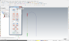
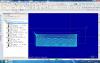
i put a 0.01mm gap in the middle of the arc, then the MCXFORSW give me the right chaining result.
thank you very much!
-
choose single and pick 1 line then choose chain partial and pick line then the radius
thank you.
it works fine in MCX. but it doesn't work in MCXforSW. it didn't give me the correct chain.
i don't know why, and i can't find the solution.
-
Or if you simply want the two lines (and want to avoid the semi-circle) just select them individually ... just like you did with the 1st one.
MCforSW will recognize that the two lines are disjoint and will make two chains out of them.
hi all
sorry for my poor english.
let me explain more clearly.
the process are as below:
first of all, i select the left line. mcxFORsw give me a chain1.
and then i select the right line. it give me a chain2. it seems everything are just fine.
but after i select the arc. something happen. there is no chain3, and the chain2 go away.
i had tried select the right line and the arc in the step 2, mxcFORsw give me the same result.
ok, then i tried to put the first line in sketch1. and put the right line and arc in sketch2. it's no help. there is still the same result.
-
I can not find the button of "add another chain", when i chain the toolpath in the sketch.
it's easy to chain in the MCX version. but hard to do that in MCX FOR SOLIDWORKS.
does any one know how to solve the problem?
much thanks!
the attache file is mcx9 for solidworks2015.

-
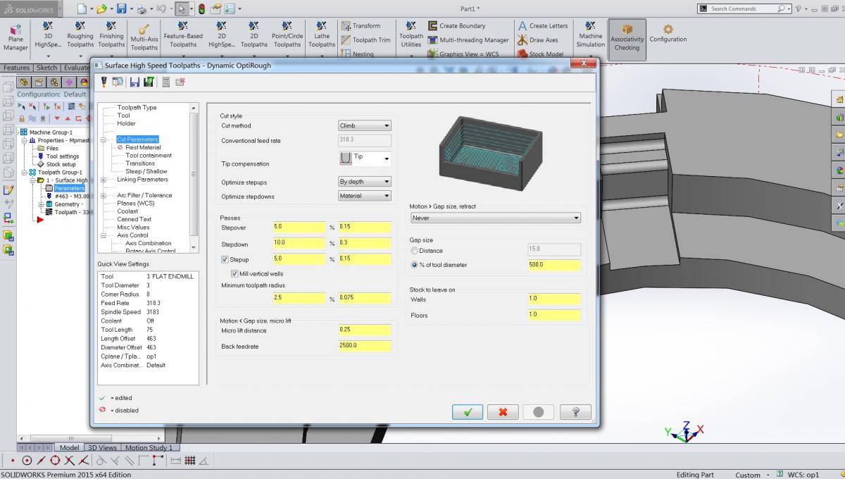
quote:
if it's a helical entry in a pocket, isn't it climb cutting no matter if you are going cw or ccw?
If your helix radius is small enough to not create a hub, then no.If you are leaving a hub, then I suppose you could arrive at that conclusion. As a rule I never create hub, so I always consider CCW a climb milling
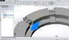
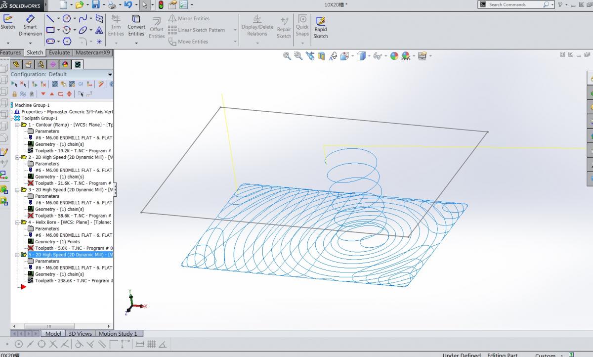
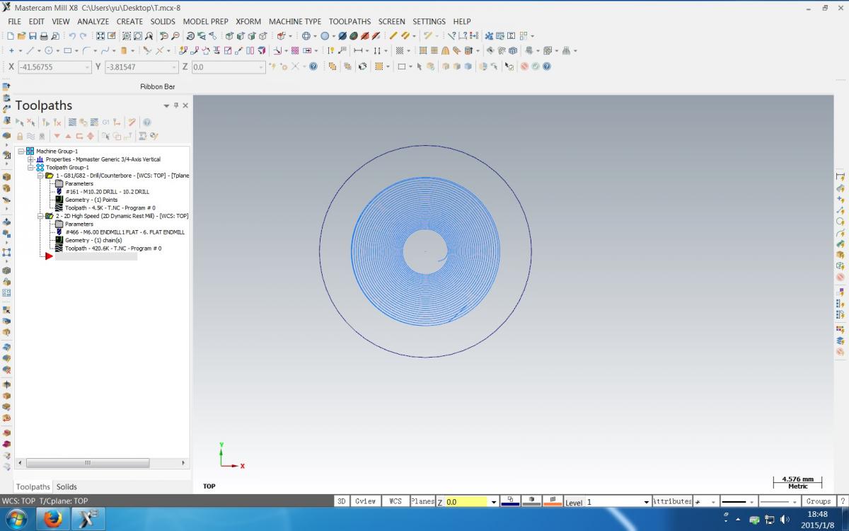
i just search for the answer of the helix entry mode of CW OR CCW.
for now, i am using mastercam x9 for solidworks 2015.
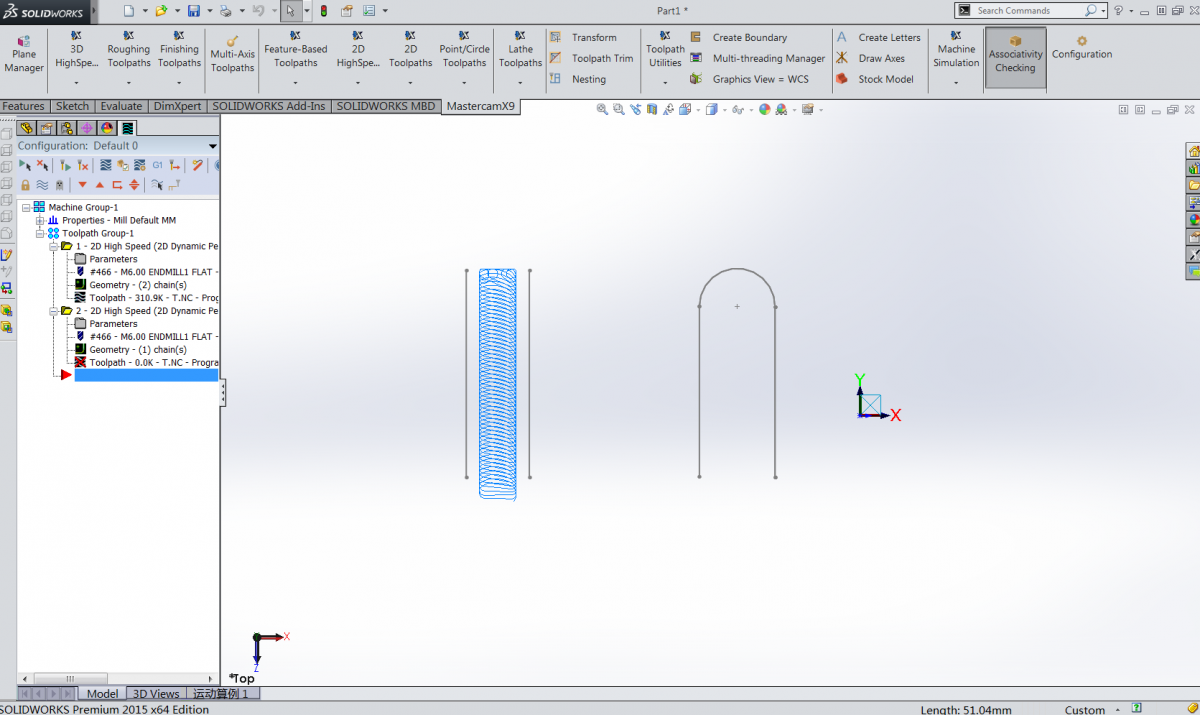
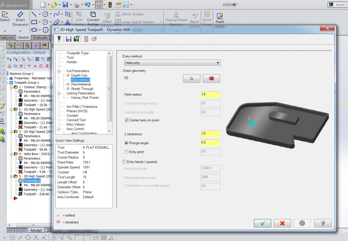
the dynamic mill tool always give a cw entry to a pocket. (for example: using 6.0 flat end mill for 3.5 radius entry)
but if you choose the helix toolpath (2d circle toolpath), the mastercam will give you a ccw toolpath.
so i would like to know, which one of direction entry is better for a flat endmill helix into a solid body.
and what's more, in this video, they choose the ccw entry toolpath.
if anyone have an idea or some experiences in this, please share with me.
thanks!!
tom


-
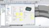
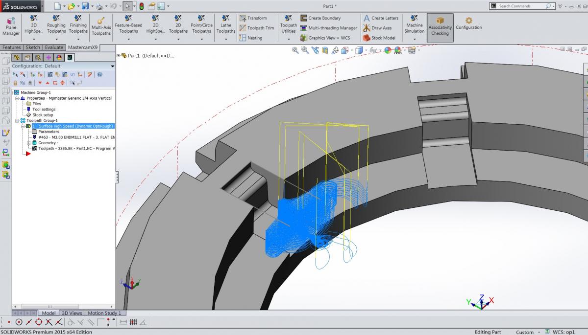
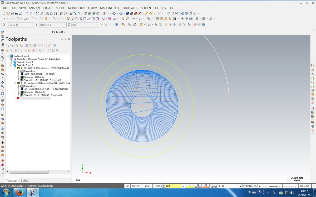
Hi everyone,
I get a sample work to do for milling several slots in a turning part.
in my pre thinking, i decide to use 3.0mm flat end mill for rough milling and 1.5mm flat end mill for finish in the toolpath.
but after i started, i get no luck. the toolpath seems much more different from what i thought.
here are the files attach, can anyone tell me how to solve the problem.
thanks!!
the version of the file is solidworks 2015 with mastercam x9
-
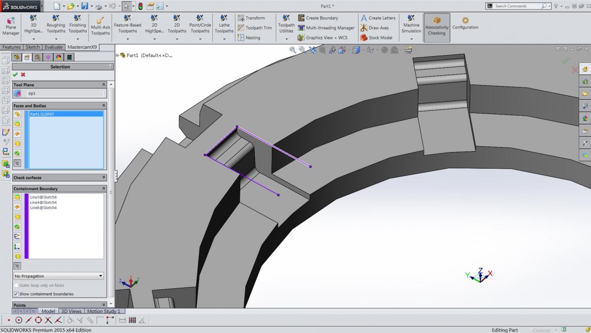
Hi Tom,
Once you select your 1st edge that will wake up the Propagate options. Propagate along Tool Plane will get you your out side chain with far fewer selections. Or better yet enable the solid body selection and select the solid. This will project a silhouette boundary up onto the current tool plane. Just click on the chains tab and delete all but the outer chain and you are done.
That is a fantastic skill.
thanks very much!
-
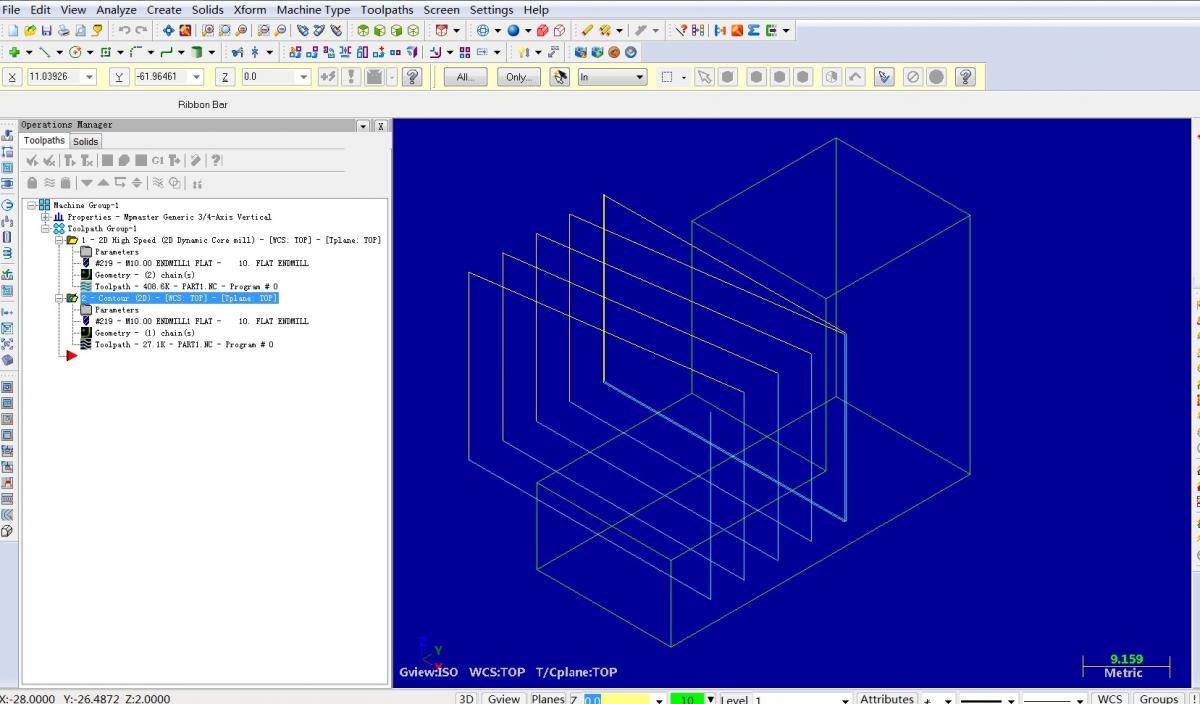
Hi, everybody.
I am trying to use mastercam x9 for solidworks (2015)
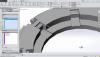
when i want to make contour toolpath (2d high speed is the same), it need me to select the outside boundary for chain.
but when the solid body have a chamfer at the outside edge, it's hard to select for chain, because out side edge had been broken to several short lines.
i want to know is there any easy way to do the selection?
need help, thanks.
Tom
-
Hello Guys,
I'm machining a 1.25 wide slot 4.5 deep using a 1.0 high feed cutter.
The first part of cutting the slot is full diameter of the tool but on the way back the radial depth of cut is .25 so I use the chip thinning formula and my increased my feed.
The question I have is how do I get Mastercam to post that out, I don't want to manually go into the program and change the feed for every depth cut.
I played with the High feed settings in Mastercam but I'm not getting the desired results, but it could be that I'm not using correct settings.
Any ideas?
TIA,
Greg
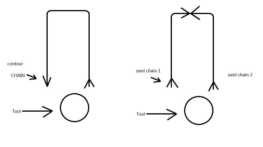
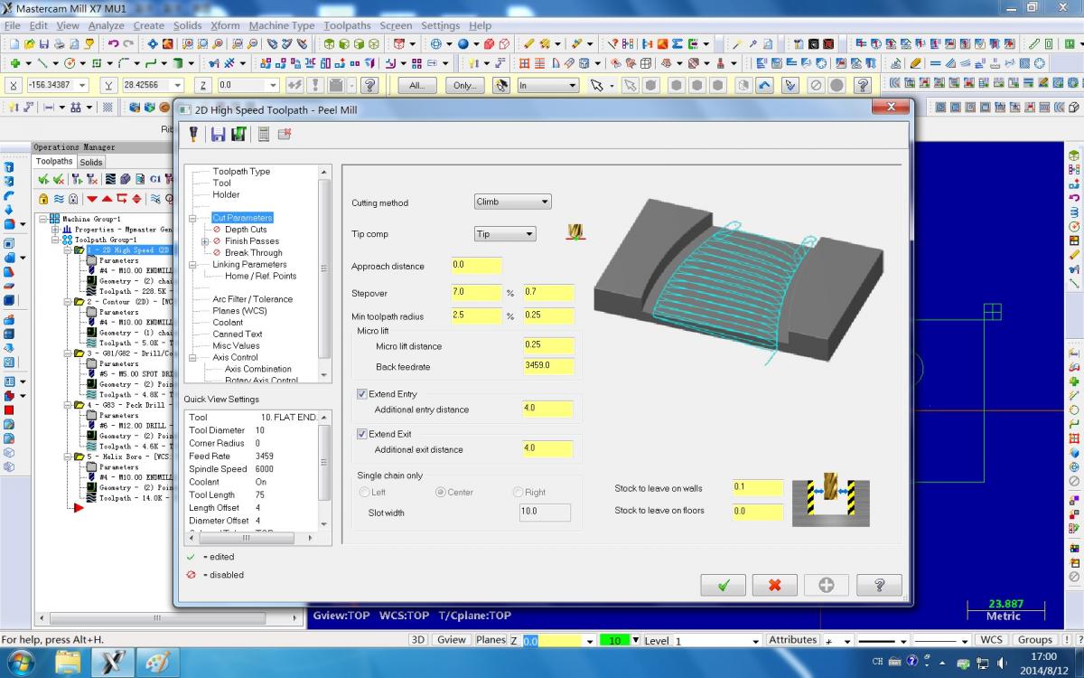
Hi, GREG,
I think you should change contour mill to Peel Mill.
In the peel mill setting, you can increase the feed rate to a higher value, and set the step over value to about 7%(it depends on the material and tools)
i post a picture to explain what i mean
hope it will be helpful.
TOM
-
-
I have a try of milling C45 steel.
Tool: 300R20D20d150L
Insert: APMT1135 for steel... (R0.8)
Speed: S2500
Feed: 1500mm/min
AE: 8%
Depth:6mm
the result is that, the insert get wearing much faster than i expected(it can't not last for 10 min), and the sounds is very loud.
Is insert end mill not suitable for HSM(CHIP THINNING)???
if anyone have a better idea of using the tool, please share with me.
much appreciated.
-
thank you all of above!!
i know what i had missed.
much appreciation.
-
 1
1
-
-
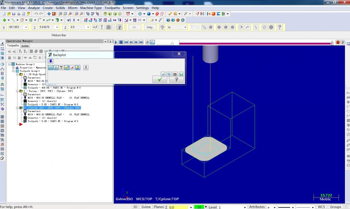
I would use contour for the feature shown. Chain the inside corner and you're done.
contour will leave some material at the four corners.
and i think facing will have a better face quality with outside entry toolpath.
thank you.
-
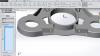
i just mill a part using dynamic core mill.
after that, i use facing to mill the rest of the material on the face and the side wall.
but i find that facing will over cut the wall side.
is there any way to set the check point of facing to avoid that happen?
i post a pic and the MCX-7 file to make it easy to understand.
any help will be great thankful.
-
If I understand you right, you have a 2D Swept path, you are trying to use tranform rotate to rotate the toolpath, When you do, they are coming out different
Try this setting in the transform


The reason it's happening, the settings of the part geometry Left/Right are changing, if you made the actual paths without rotation you would see you needed to use different setting in the paths to get them to cut properly, so in transform rotate, the initial setting is to use geometry, so it tries to use your geometry settings, and on this path it will be a problem, so by switching it to NCI, you're now using the numbers inside the NCI file and it is those that are being rotated. On most transform rotates, the geometry setting works perfectly fine but there are some toolpaths and that will need to use the NCI option
hth
I took your file and rotated manually the geometry and re-chained to cut in the same manner as yours, notice the different setting to get the same cut motion. That is why the Geometry option on this path will fail
thank you very much.
it's the key point.
-
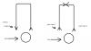
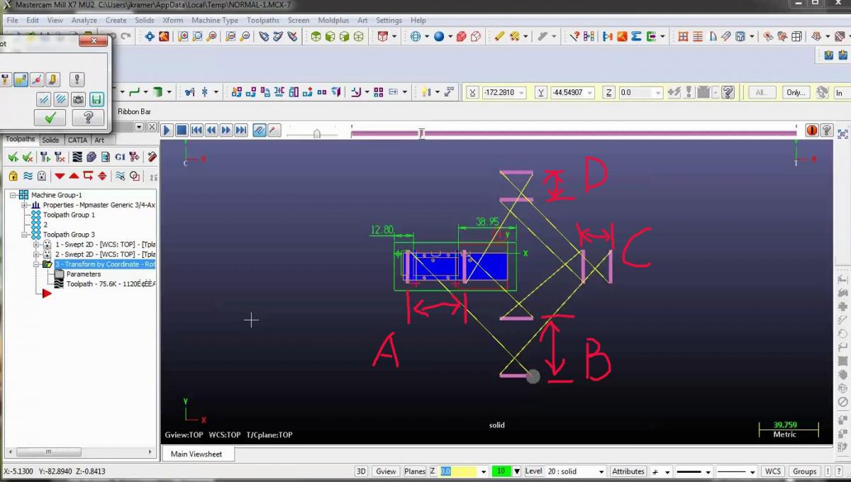
I would watch this video and see if this what you want.
thanks for your video.
i print screen to figure out what i am not understanding about.
A=B
C=D
but A not = C
why??
-
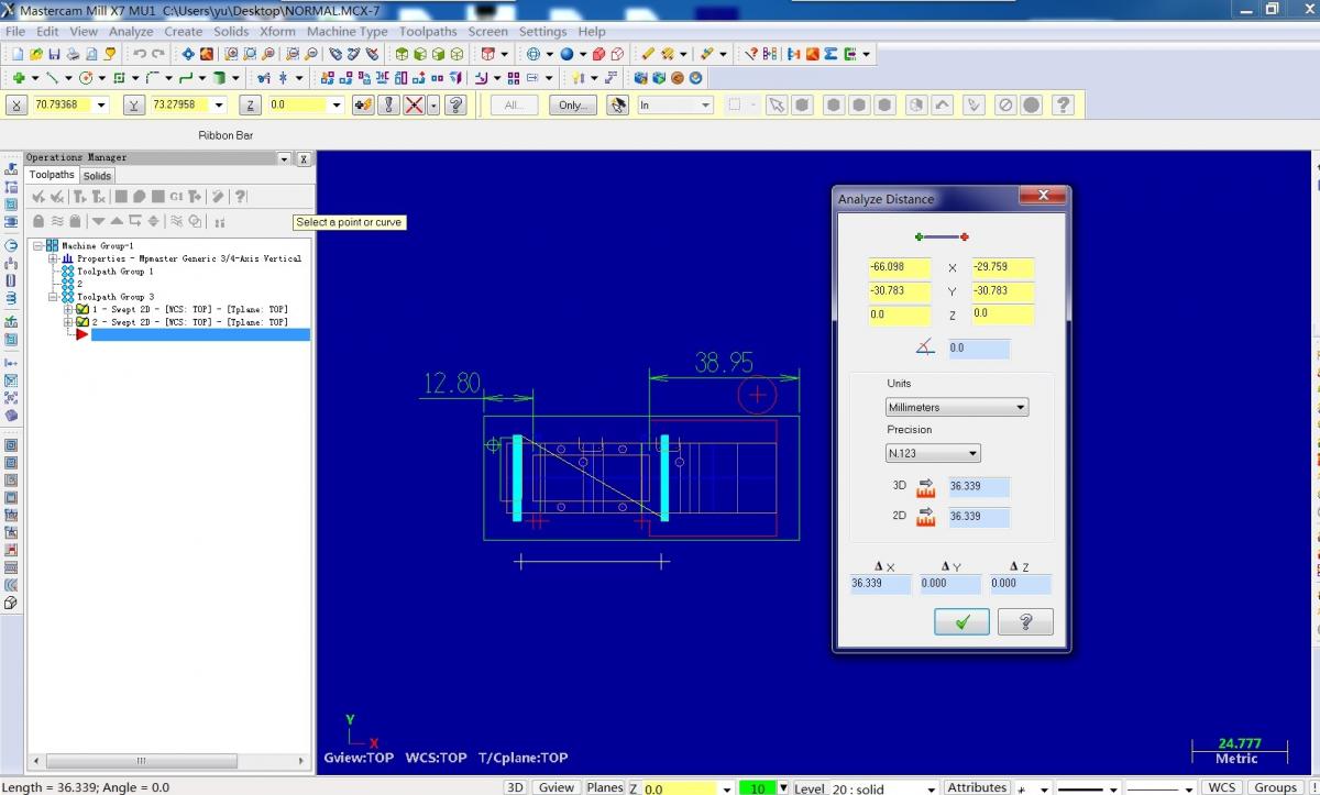
Are you trying to rotate a file or transform a tool path to all locations?
i am trying to rotate the toolpath. but after i rotate it, i find that the distances between the two toolpath change sometime.
so i want to know what's wrong with my action.
i use Mastercam X7. menu---Xform---Rotate command.
you can down load the file NORMAL.MCX-7 and the 180DEGREEISNOTOK.MCX-7 above.
it's so different between the two of them.
thank you.
-
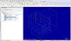
hi all,
i get a problem of using MCX7 while i am trying to rotate a drawing.
i use the menu(xform---rotate--select all drawing, move, and input the degree)
i find that it's normal after i rotate 90degree, but it will get a shorten distance with 2 toolpath more than that.
to be easy for understand what i am talking about, i post all the files here.
if you get any idea about this, please tell me.
any help will be much appreciated.
-
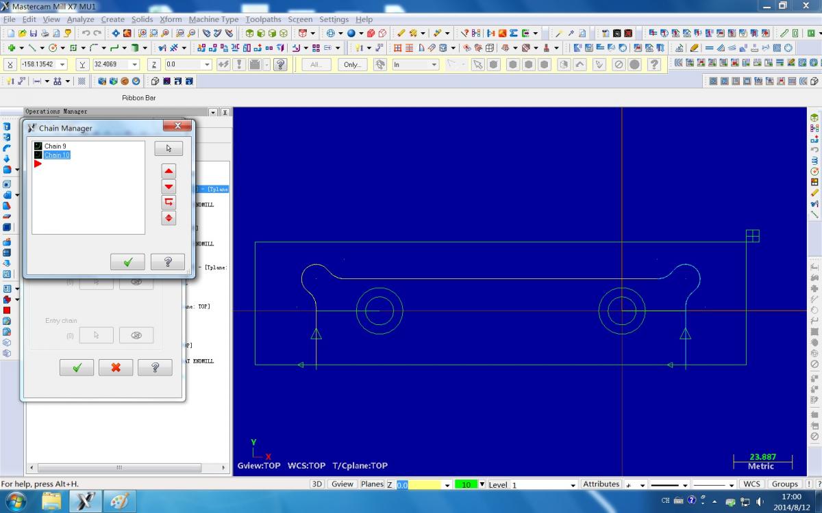
With Peel Mill the chains should be parallel and should not touch (the chains should be side-by-side). Now even though I say this, I have got the toolpath working by changing the chains so that they are the same length and touch in the middle (but this is still not the way the toolpath is designed to work).
great!
thanks a lot
-
it confuse me much, the right upper side will be ignore automatic.
I USE peel mill.
could anybody help me, please?
any help is thankful.
-
hi,
i just installed MC v9.0 on windows 7. it works good.
if you get some trouble in useing MC9 on win7, just right kick the icon of mc9, and selcect options---competion mode of WINDOWS XP, it should work.
hope it will help.
I
I am currently using mc9 on windows 2000 operating system. We will soon be upgrading with new computers with windows 7 and wanted to try and find out if there were any compatibility issues , and if so what are the remedies?


How to remove the retract action in 2d contour with multi chain?
in Industrial Forum
Posted
i have a part which have many island on the surface.
when i try milling, i find the MCX keep retracting between chains. and the tool keep going up and down, cutting air.
is there any way to avoid the retract actions??
i try to add some points between the chains for guiding the tool not retracting, but MCX seems not smart enough to know what i want it to do.