


jbelle7435
-
Posts
58 -
Joined
-
Last visited
Content Type
Profiles
Forums
Downloads
Store
eMastercam Wiki
Blogs
Gallery
Events
Posts posted by jbelle7435
-
-
Go into your mastercam documentation and it will answer a lot of your questions and tell you step by step.
yeah now getting tapering to work in CAM I might got but now tapering on the WEDM Machine is tricky. I am missing info to get the back plot in our WEDM(Mits 90HA). 1st I have to get the MC working and then I still have to get the WEDM working as well.
-
That is fine I don't want to break your comp! There was a 1 degree taper I bet. Hard to notice if the holes have different diameters. I will do this manual break to help me. I saw the Direct 4 axis. Will check that out.
DAMN!! I did the Direct 4-axis on the simple drawn circle and damn it shortened that code and used the G02 command woot. I was thinking it was there but you opened up a nice door for that one
-
I noticed on your previous files you had the same diameter holes at top and bottom. I'm not opening your files today as it caused problems on my computer. Note ALWAYS MANUALLY BREAK YOUR ARCS AT 180 DEGREES. iF NOT i HAVE FOUND IT POST OUT WRONG U and V but looks fine on backplot. Always use Direct 4 axis instead of 4 axis taper and it will be smoother on your code. Direct 4 axis will not work with splines though.
That is fine I don't want to break your comp! There was a 1 degree taper I bet. Hard to notice if the holes have different diameters. I will do this manual break to help me. I saw the Direct 4 axis. Will check that out.
-
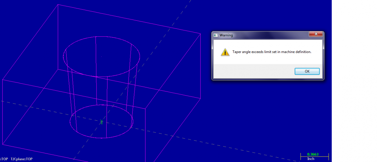
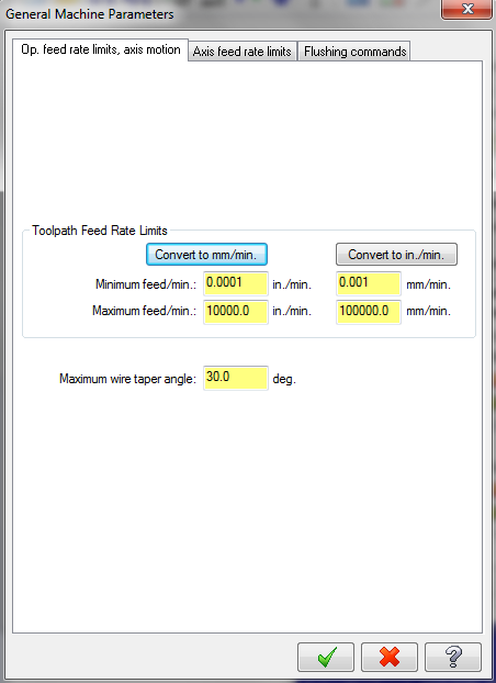
This is my file with the loaded .STP with a simple 5 degree taper. But it says I exceeded my angle limits and even when it does work it goes around once but the wire goes crazy and def would not work in the machine. It says my max. taper is 30 degree and I am at 5??? Wonder what else I am missing to fix this..

-
I think I got what I was looking for....
1. Setup a new file
2. Added bottom circle and upper larger circle
3. Set my thread point at center of lower circle
4. Tool path--4 Axis-->Chain Selected the #1 Thread point, #2 Lower circle #3 Upper Circle in that order-->Check Mark-->Check Mark without any changes and wallah. I tested it and one wrap around. I wonder why it was going all crazy on me yesterday. I will attempt the same thing with a model from inventor because thats my goal! Not to just draw from scratch. Worst case is if I have to then thats life I guess but it should be easier than that with all the models I want to use in the WEDM!
extra:
What I noticed in the NC code is it does not make this taper with the G02/G03 commands. Just got linear movement on the top and bottom. I wonder is there away to shorten all those point unless that would be make a polygon instead that I don't want. If not then I let the machine do the talking with the code...
-
no prob. monday it is
.gif) . THANKS
. THANKSI will get this tapered down if it kills me and maybe Del ...
-
one sec
see attached. I see one pass and no reverse but still does what it wants without me telling otherwise...
I am just trying to figure how far or close I am to what I want. Center to circle and then one circular pass at the tapered angle(Top and Bottom) and back to the center!!
-
Jbelle, Look at this as an example of a 4 axis path taking 2 burns with a reverse pass.
Note: When I opened it was missing the power library but I dont' think that will have any affect. I notcied the 2 burns with a reverse pass.
When you are WEDM a tapered hole is that normal with a "path taking 2 burns with a reverse pass" because it seems I can not control these actions? That's the main thing I am trying to figure out if that is normal and if so then its fine but if not then I want to figure how to do one circular pass.
Its like I am not asking for a reverse pass but it does it anyways???
-
If you have it set for 2 passes and are using reverse then it would be ok.
Maybe I missing something. See the attached.
I have the sync mode "by entity" for all (chain wire point 1 and chain 2 and 3 which are the bottom and top circles)
BTW, thanks for all your help.
-
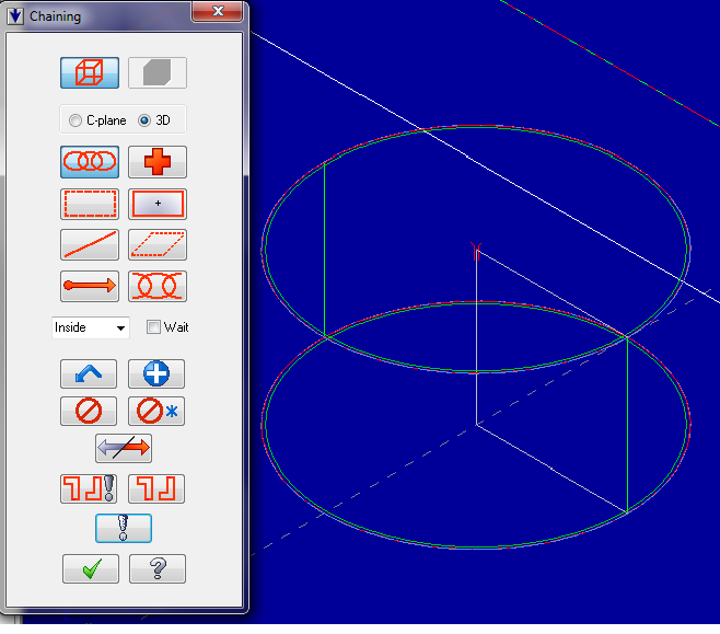
Jbelle, forget that auto shi* and set it to left or right, forget setting it to computer and set it to control. get rid of the branch lines from connecting top and bottom, BREAK THE ARCS AT 180 DEGREES MANUALLY, select 4 axis,chain, select the bottom thread point, chain the bottom circle,chain the top circle only, set your parameters and if part is sitting on table set xy height at 0, uv height at top of part.always use sync. Use by entity when you have same number of entities in top and bottom, use branch points when top and bottom must be connected so wire knows how to syncronize them.
I am sure I followed you. When I run it, the wire travels from the center to the outside then comes around CCW to that same point thiniking its going back to the original center point but then goes back CW back to that point then finishes off? Is this normal for tapering holes doing that extra reverse circle? or is it supposed to travel once around and thats it?
-
set sync to " By Entity" you have it set at none
hmmm I started tinkering with that...I did notice that earlier in a thread of mine or not ..
Prior to selecting each line I set the "By entity" and nothing has changed...
-
now I think about it. Maybe that extra chain is occuring because I selected it third but then how do I combine the two holes into one chain for one revolution only hmm??
-
Hey,
For some reason when I:
1. Toolpaths-->4-Axis
2. Chain select [The Center Thread Point, The Top Outer Ring, The Bottom Inner ring]
3. Select Ok and Ok to my parameters
4. It says "You have not chained a thread point nor enter a lead distance ....?
5. Then it still works with the Taper
6. except it does this extra loop that I did not ask for ?? 1st it does CW and then it goes CCW and finishes off ????
7. And why won't it let me reverse direction for the chain when I am chaining my lines...?
6 and 7 are my issue right now.
PS. When I did spit out the NC file is there a way to shorten those X Y and U V coordinates if I just have 1 circle with a start point and end point even though I am doing a taper or that is how it is for four axis?
-
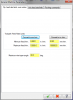
Jbelle, I am not familiar with your machine. I would think the H number is the offsets for each pass and the E692 are your power settings.F is probably your feed rate which also changes for each pass. I would assume both numbers would change for each pass you take. You should be able to set those conditions at your machine after you have loaded your program in the machine. Maybe someone else familiar with your machine could be of better help.
Good news recently is I am doing test passes without the material but its going too fast still because the wire kept on breaking with the material so I am trying to figure why it worked previous(slower moving).
-
Jbelle, To obtain that accuracy I would take 1 rough pass and 3 skims. The H values are your offsets for each pass. They get smaller for each pass since the power settings are also different for each pass. Usually the first pass will leave about .002/side for 1st skim, about .0005/side for 2nnd skim, and .0002/side for 3rd skim. Each pass is leaving less to burn out and using lower power setting to obtain accuracy and finish.
A rough pass only will put you in the .001 range depending on thickness of part. I recommend you have your employer send you to some training for both the wedm and mastercam. It will help you a lot to understand what the wedm is doing.
are you familiar with lines of code that look like
N0001 F.09 H1 E692 M90;<---THIS IS WHERE THE ROUGH CUT AND SKIMS WILL OCCUR I assume
N0002 G01 G41 M88 X0 Y-.1250
N0003 G03 J-.2500
Some concerns..
1. Do I need the H1 in there if its defined already in the E692?
2. Do I need to actually start off with the rough cut of the E value specified??
3. When I make skim cut 1,2,etc do I copy the lines N0001,N0002,N0003 and place them below one another while updating the E value accordingly for the skim cuts(E691,E692,etc.)
example...
N0001 F.09 H1 E690 M90;
N0002 G01 G41 M88 X0 Y-.1250
N0003 G03 J-.2500
N0001 F.09 H1 E691 M90;
N0002 G01 G41 M88 X0 Y-.1250
N0003 G03 J-.2500
N0001 F.09 H1 E692 M90;
N0002 G01 G41 M88 X0 Y-.1250
N0003 G03 J-.2500
-
I am running a Mitsubushi HA WEDM. I ran my 1st program for a .5000(+/-.0002) DIA hole only. The H value I had was H1 and it was pre-set to .0060".
With CCW and right compensation, my .5000(+/-.0002) DIA hole came out to .4975 so before I start making more passes to clean it up to a .5000 hole (ex. 1st .0006 and a 2nd .0012 large holes around it what does this H represent and if I had it set already at .0060 was that my 1st mistake and if H was another value could I get my .5000(+/-.0002) hole within tolerance on
ONE PASS ONLY??
Update: I found out about these Epak values and an H is already defined. Is it possible that the new H defined was overlapping the originally one. I still need a good understanding of H so I can take the guess work out trying to create a .5000(+/-.0002) hole like a good exmaple.
-
Yeah I was noticing that why multiple commands when the tool does not do anything else besides revolve 360?? Thanks for the heads up on that. I learned this code in college for a quick subject in one class that I barely remember. I don't mind going through line by line making sure what is coming out makes sense to me and then the machine its used on.
I did update my options and this only worked once. It has the same as above but still divides the circle up as of now.
Note: I am using wire mode
It worked this time. Weird.
-
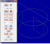
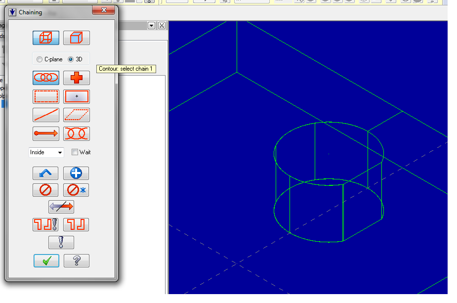
hmmm I did notice the double vertical lines there.Wonder if that could be a factor,...
update: no wire hidden frame option took that off and made it a single line
-
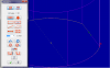
see file attached. I think I got the circle only version making sense now. Now its this one with a flat added. Not that much different!
-
here is a perfect example why I am stuck...
I have everything set at the bottom. Chained the thread point and it chained the flat and circle but then did not finish it off and now I can't select anything else. I will attach this file also if it helps??
-
Yeah I am running into it helps and then it does not help situations. I just want some consistency for once. I will see what I can do with that. Thanks.
Like everyone wants to do is load in a part,, make the runs to my liking and thats it. All I been seeing is non-sense but I hope to remove that soon.
When I pick chain for selection I can choose the thread point but I cannot select the top circle. That is what is frustrating me!
 Is it because its a 3D model from inventor and not a sketch/wire model. Should I draw a sketch circle on top to be able to select it and it will work or should I select solids and work with that??
 -
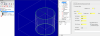
When you come from the outside of the part it makes it confusing for mastercam. If you come from the outside and want to wire the hole to .500 you will have to change your offset to right G42 even if you are going CW. You can see this in backplot where the wire stays to the outside of the part with the G41. I would drill or hole pop a hole in the center and do it like this.
Looked at your model.
1. I know how to place the "Create thread point" at the center and saw you created it inside instead of from an edge and that is how I will be making more parts.
2. How did you chain the point and then let it go straight to that quadrant point without drawing a line. What channing command did the trick. I am trying window,point, etc and does not work like your did. Thats why in my model I drew a line to guide where the wire is going but I still ran into problems. If I can get comfortable using the selection command that might def help in the long run.
3. I noticed your model is drawn from scratch. Mine came from Inventor. Does that change how the lines are selected?
In the options box I see it selected as break closest entity to thread point. When I have this selected it starts the cut point always from the origin(outside) and when I select start chain at point it works from the center.(Update, I don't think that does anything)
I added a second thread point to the bottom the the hole as well...Would that make sense?
-
You need to take in account for finish. If your just dropping a slug ±.002 depending on material. You should be taking a finish pass at a little power setting to get better finish to hold ±.0002.
This what I learned around closing time after I coded the CCW with the G41 command. Now I am on the small "safe" side I can work my way to the tight .5000 tol and +/-.0002 is in the ball park I need! Trial and error work better with more knowledge added each time
-
I have a practice block. Selecting this stuff right now is the hardest part because then when I review it comes out all crazy.


PATH CONTROL
in Industrial Forum
Posted
WIRE
I am still having trouble controlling the path the wire starts at. I got the circle down and thats working fine. Now If I had a square or linear path to travel when I finish up chaning it decides to go from the center to one of the corners of the cut and I can not have that(Pre-determined angle). I need to control from the center point to where the next location will be and when doing so it still decides to go to that corner or the cut and start there from the 0,0.