


Bwank1124
-
Posts
20 -
Joined
-
Last visited
Content Type
Profiles
Forums
Downloads
Store
eMastercam Wiki
Blogs
Gallery
Events
Posts posted by Bwank1124
-
-
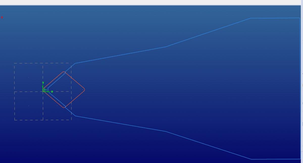
I am trying to create custom lathe tools for a multus. I have a face and turn tool that is mounted on the b axis at a 45° angle. I need to rotate the A around 180 to get my post to come out with position 4. Does anyone have experience with this? I attached a picture of how i got the tool drawn which works fine for position 3.

-
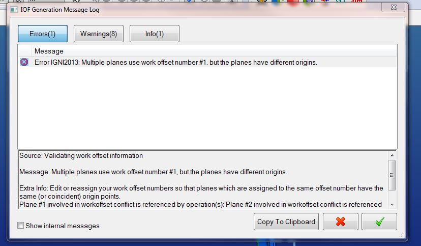
Why on the main spindle can I run g54 for milling and turning operations but on the sub spindle I get the error when trying to run g55 for both milling and turning? I sent my file into QC, I have had this happen a lot so I must be doing something wrong but just not sure what I am doing.
-
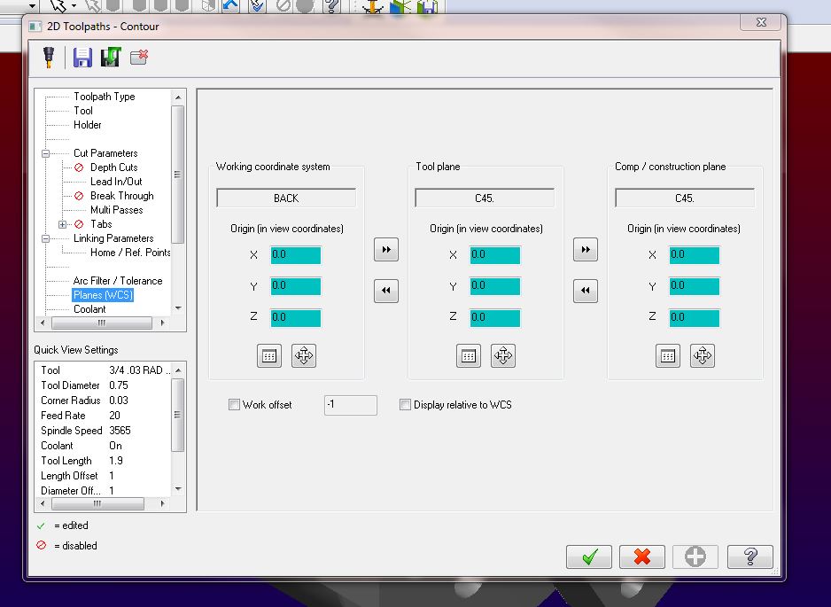
I am new to mill/turn and I am trying to program a part and pick it off on the sub spindle. Everything is fine on the main spindle I don't get any plane issues. When I transfer it over to the sub spindle and I have a milling and turning op on the sub spindle I get an error message "multiple planes use work offset #1, but planes have different origins". I haven't moved any origins or touched any of my WCS so I am not sure what I am doing wrong. I just know that the main spindle uses offset "0" so I don't think I would need two different offset numbers on the sub spindle. Any help would be great.

-
Yeah no lower turret. We have been running without the mill/turn. Right now the guy at the machine programs everything he can using IGF. Then if he gets stuck we will make a program up for him. We know in the programming room that this probably isn't the best way to go but we need to let the guy fail a few times and take a couple days so we can start doing more off-line programs.
-
Thanks guys, I was just wondering. There is talk around here to get a better post and go full blown mill/turn so we will see what happens but for now I will give that a try and see what happens.
-
I am not sure. This is what the post says for mill toolpaths.
(#MILL TOOLPATHS:
#Mill Layout:
# The term "Reference View" refers to the coordinate system associated
# with the Mill Top view (Alt-F9, the upper gnomon of the three displayed).
# Create the part drawing with the the axis of rotation along the X axis
# of the "Mill Reference View" with the face of the part toward the side
# view (Mill Reference View X plus direction). The Y plus axis of the
# Mill Reference View indicates the position on the part of C zero
# (View number 3). The right or left side view are the only legal views
# for face milling. The view number 3 rotated about the X axis as a
# "single axis rotation" are the only legal views for cross milling
# except for axis substitution where the top view is required.
# Rotation around the part is positive in the CCW direction when viewed
# from the side view.) -
So I am messing around with a sample part and getting use to setting up planes for a mill/turn. I saw the pdf for setting up the planes which works great. I am just wondering if I should have my WCS set to top or back?
-
Playing around with X8 it looks like this is fixed.
-
 1
1
-
-
I am trying to setup a master file for a lathe program in X7. I have to program the part for two different okuma machines, one is a LB-15 single turret and the other is a LU3000 with upper and lower turret. The problem I am running into is I want to make one file with both machines underneath it. My problem is the tool list keep combining the unused tools when I reopen master file. I want to keep the unused tools separate because on other parts I may need them. Any help or advice would be great.
-
Obeginski I am not seeing the external post button like is shown in the help menu under simulation. Where did you find this?
-
I am having problems with my move list under the sim not reading relative to my part zero point. It seems to always be to machine zero. How do I change this? I have adjusted the drop down under the sim setup to relative.
-
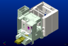
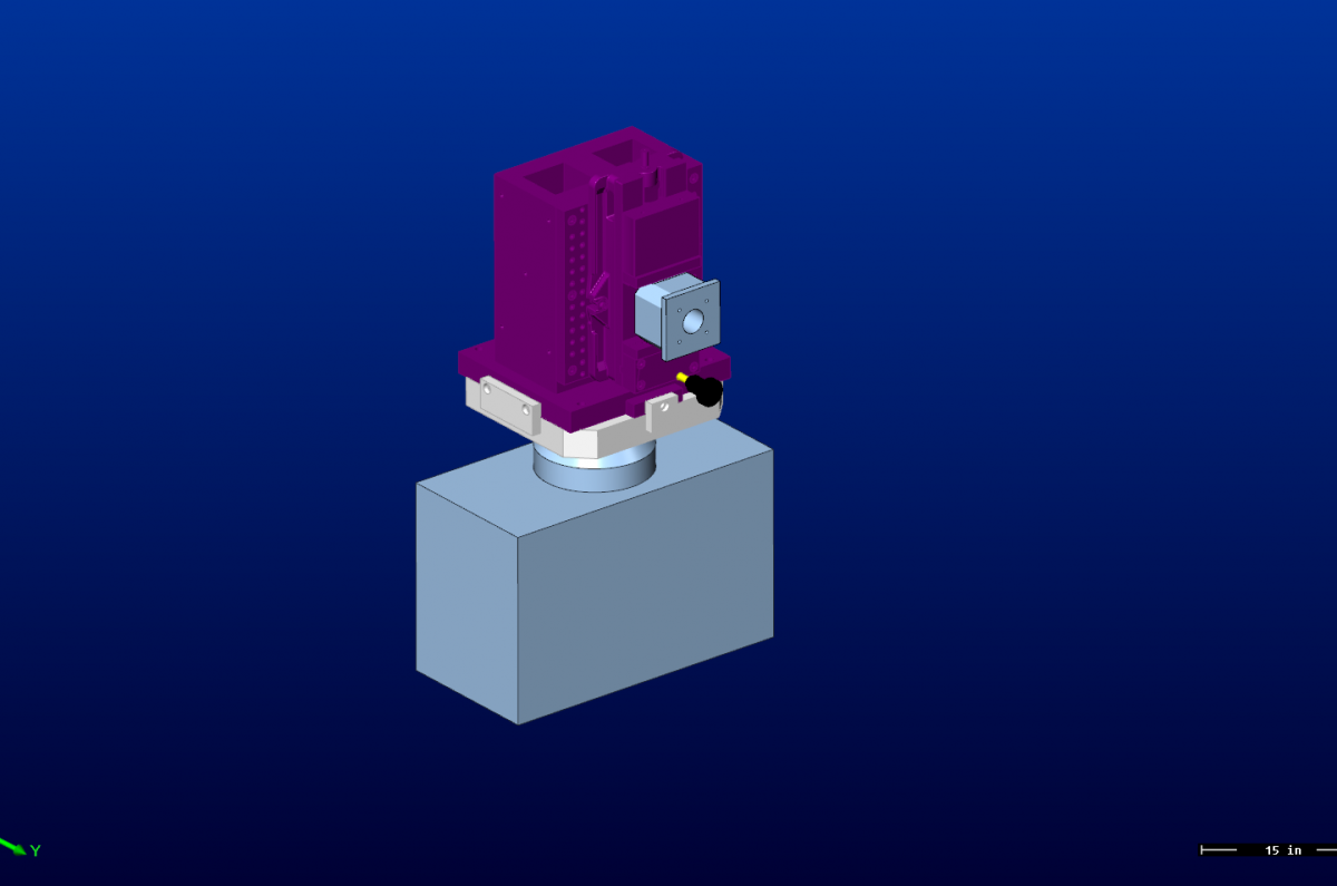
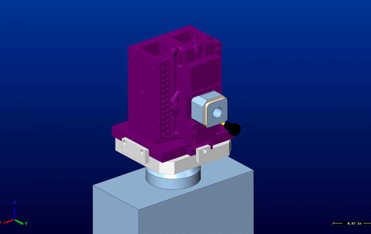
Anyone play with the simulation for mill/turn? I am going to dive into building a Okuma Multus.
-
Where are you guys getting your stl files from to build the machines?
-
I just wanted to see if people were using it. What their thoughts were on it. I am really new to the X version so this was a big step getting this fart with the machine simulation.
I am also having that same issue with the tool not retracting. Is there any work around on that?
-
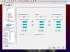
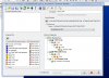
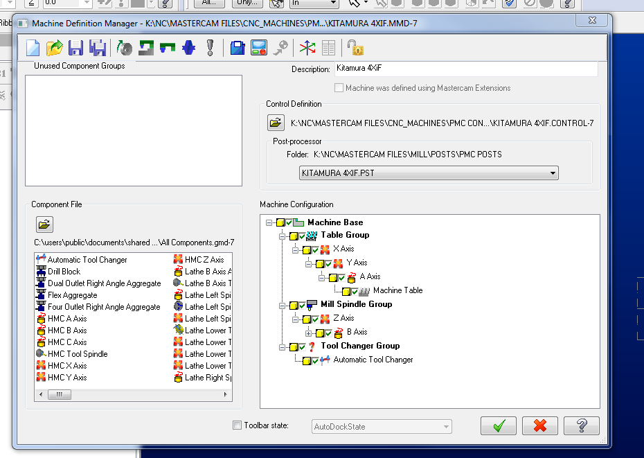
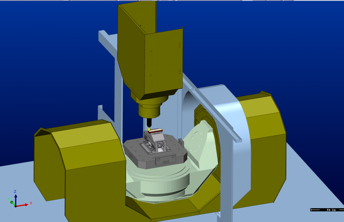
Is anyone else using the internal machine simulation with mastercam? I have started using it since we only have two seats of vericut and I am the odd man out right now. I'm just wondering if other people have experience using it. I did pretty much a basic setup right now of a couple of machine, two horizontals and one 5-axis. I attached a few photos. I was also doing some digging around under the machine def manager and see there is a machine configuration. Anyone play around with these? I posted a photo of the machine def. lower right corner is machine config.


-
1
-
-
I got it. I had to turn off the EA manager and all my levels came in right.
-
I did that. I should specify that I am trying to import solids from another mastercam file. Is there a difference there?
-
Does anyone know how to import another file but maintain all the levels and color from that file being merged?
-
I haved drilled 1/8" holes 5-6" deep in 6061 a lot at a previous place. I usually pecked at half the diameter of the tool and have had great success. That was using a Guhring series #503 I believe.

Creating Lathe Tools for Mill Turn
in Industrial Forum
Posted
I got that part. Its creating the tool geometry as far as where the center point of the nose radius needs to be. In my picture of the tool I have drawn I got the B axis at 45 and the A axis at 180 and it posts out the right code. But lets say I want to use that same tool at B45 and A0 do I need completely different geometry of my tool? Like for example mirror it over the X axis?