


Giang-TT
-
Posts
22 -
Joined
-
Last visited
Content Type
Profiles
Forums
Downloads
Store
eMastercam Wiki
Blogs
Gallery
Events
Posts posted by Giang-TT
-
-
It took me some time to catch what you are mentioned about.
I think I found one different thing between my G68.2 approach and yours, that is:
- With my simple approach, I used the toolplane vectors to get the i,J,K value directly. With this method, my tilted plane's X&Y may not align with the machine X,Y axis after applying the G68.2 (e.g. X100. command will cause both X and Y axis to move)
- With your method, the tool plane's X&Y axis will be rotated to align with the machine XY axis after applying G68.2 . Am I correct?
I don't know what is the actual purpose of it, is it just for a better visualization?
Thanks again for your comment, I hope you guys can still understand what I say with my English.
---------------------------------------
Update for the function. Now I'm able to control the n_tpln_mch value using the mill5$ variable.
if mill5$ <> 0, [ top_map = 0 ] else, [ top_map = 1 n_tpln_mch = top_type !n_tpln_mch ] -
On 2/21/2024 at 11:28 PM, Colin Gilchrist said:
The important thing to understand is that some functions were created inside the 5-Axis Post "early in the development" of the Post, and that architecture can be used to support other things. This is the case with 'n_tpln_mch'.
It was originally used to support Nutating Heads/Tables for the G7 function, and using only "mechanical kinematics" to calculate the correct output for a Tool Plane, giving us XYZ P/S (Primary/Secondary) output.
n_tpln_mch gets initialized to '-2'. A setting of '-2' indicates "5-Axis". A setting of "-1" indicates "a path that is not Toolplane Based (3+2 output)". For example Axis Substitution where the input is a Tool Plane, but the math tells the Post to "wrap the rotary axis".
n_tpln_mch gets set to 'top_type' if 'top_map' is active. Otherwise, the post does some other calculations for 'n_tpln_mch', and eventually sets it to 0-4, indicating the type of internal processing (mapping) to achieve the desired output for angles and coordinates.
When 'top_type' is set to '5', then 'n_tpln_mch' also gets set to '5', and then it just overrides all the automatic Nutating internal logic calls, and just calls the "Custom settings, ptop_type_ax and ptop_type_lim" instead.
When G68.2 is implemented using the default architecture For a non-Nutating machine, 'top_map' should be '1', and 'top_type' should be '5', and the only values n_tpln_mch should have are -2 for 5-Axis, and '5' for Plane Mapping (Tilted Work Plane) output.
It is only when 'top_map' is off or 'top_type' is not set to '5', when you'll get the value of 'n_tpln_mch' set in the range between -1 and 4.
In a properly configured Post, using the default architecture, you should only see -2 or 5, or maybe -1 under certain circumstances.
Just for clarity, the only valid values I believe the post should return for n_tpln_mch are: -2, -1, 0, 1, 2, 3, 4, or 5.
I tried posting some 5axis toolpaths ( swaft machining/5axis helix bore/5 axis drilling) the n_tpln_mch was initialized to '-2', then it got the value -1. So, looks like "-1" is for multiaxis toolpaths.
But when I post a multiaxis toolpath with another toolplane-based (3+2) toolpath, the n_tpln_mch can not get back to 5 when it passed through the (3+2) toolpath. Do you have any idea on it Colin?
-
On 2/24/2024 at 1:08 AM, Greg Williams said:
Giang,
If you use m1$ to m9$ the plane will need to have the correct orientation, if the plane is not correct to the final machine orientation then the code will be different to what the G68.2 block is outputting.
Hi Greg, sorry for my english, but what do you mean when you say "the plane will need to have the correct orientation"? In my post, I'm still using the s_out and p_out variable to get the rotary angles for the table to index (before calling the G68.2)
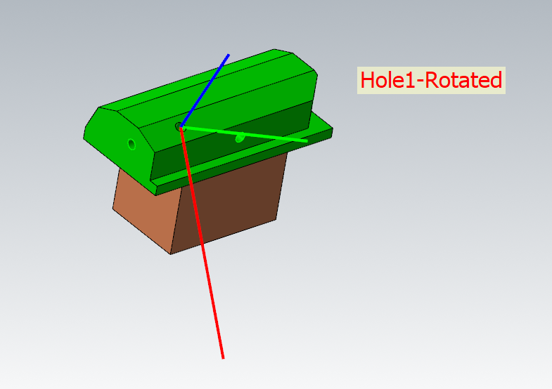
N120G54G0G90C180.A-23. (those angles are taken from s_pot and p_out) N122G68.2X40.Y24.1802Z45.4073I0.J23.K45. (The I, J, K values are calculate from mi1 -> mi9)QuotePost ops 8 and 9 of the attached file, you will see if your calculation is correct, both ops should give the same G68.2 IJK angles.
I don't think I,J,K have the same value when those 2 planes are not the same orientation for X and Y, are you sure?
I tried posting your file, this is what I got from my post (it is modified for a table table AC machine). The output A and C are the same for both planes.
G68.2 X40.Y24.1802Z45.4073 I0.J23.K45. for Hole-1 Plane (C180 A-23)G68.2 X40.Y24.1802Z45.4073 I0.J23.K245. for Hole-1 Rotated Plane (C180 A-23)(------End Tool Measurement ------) (---Tilted Work Plane---) N118M11 M13 N120G54G0G90C180.A-23. N122G68.2X40.Y24.1802Z45.4073I0.J23.K45. N124G53.1 N126M10 M12 (---Tilted Work Plane---) N128G0G90X0.Y0. N130X0.Y0. N132G43H16Z50. N134G81G98Z-10.R5.F250. N136G80 ptoolend$ ptlchg0$ (HOLE 1) p_goto_strt_ntl N138G91 G28 Z0. (---Tilted Work Plane---) N140M11 M13 N142G54G0G90C180.A-23. N144G68.2X40.Y24.1802Z45.4073I0.J23.K245. N146G53.1 N148M10 M12 (---Tilted Work Plane---)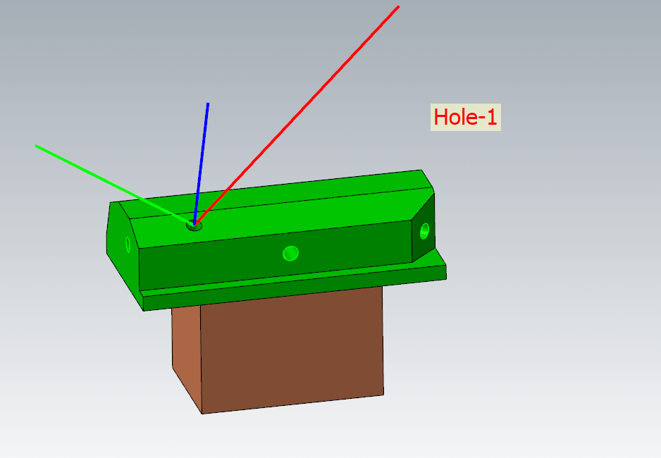
 Quote
Quoteif you have XYZBC or XYZAB then you will need to run the calculation or create a matrix and rotate the 2 angles you have back to AC orientation.
Can I ask what is the purpose of this "back rotation" while I'm just using s_out and p_out to get the angle value and using toolpath NCI (m1-m9) to calculate the IJK?
Thank you a lot for all off your comments.
-
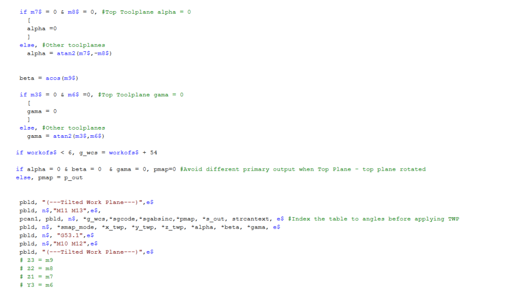
I don't have much knowledge and experience with the vector functions of the MP language, so I tried to minimize the modifying work as much as possible to make the G68.2 work.
This post is created for a rotary table type machine. In my G68.2 it only has one option formatting - using Euler Angles IJK.
In my post I created a new post block p_twp for calculating the value of X,Y,Z origin and I,J,K angle - based on the data read from NCI (1013 and 1014)
After doing many tests it looks working correctly. But as mentioned before, there is one variable, the "n_tpln_mch" , it appears in some existing post block and makes me confused, it also changes the result of the output code. So if I know what exactly it is, I can still sticking with it, if not, I will try a different way.
Thanks again Colin, I also learned a lot from your post course videos.
-
Hello,
I'm working on the generic 5X post to add the tilted work plane (G68.2) function to the post. But there is a hidden variable - "n_tpln_mch" which I really want to study clearly about.
I guess it relates to the "top_map" and some other stuffs in the binary file. During the tests, its value makes me confused. I want to ask about all of its possible values and the meaning of each value. Wondering if anyone can help me out, or this section should be kept secret.
In my post, the "top_map" is set to 1, when I have a true 5-axis toolpath (mill5$ <>0), the "top_map" is set back to 0.
During the tests, I realized the "n_tpln_mch" has different values depend on how I posted the toolpath.
The case is: I have a true 5-axis toolpath (5-axis helixbore) following by an indexing toolpath (Area roughing). Using the post debugger, I checked the value of the "n_tpln_mch" variable when it passed through the indexing toolpath:
- When the indexing toolpath was posted alone, the n_tpln_mch = 5, I got the G68.2 worked correctly
- When I posted both toolpaths together, the n_tpln_mch = -1 when it passed through the the indexing toolpath, the G68.2 then skipped.

I think I will add another condition for this case but it will be the best if I know what "n_tpln_mch" exactly is.
Thank you.
-
Thank you all for the replies, I tried them all and here is some updates:
On 1/17/2024 at 9:46 PM, crazy^millman said:Force A tool change between each operation.
Yes, this helps - but it also outputs some tool change codes in the program, which I want to hide.
On 1/17/2024 at 11:11 PM, Aaron Eberhard said:One way that would absolutely work would be to put a manual entry op between the two operations, that was just G0 C0. B0. to index it that way.
Without your specific post it's hard to test if this would work, but you could try playing with these misc values
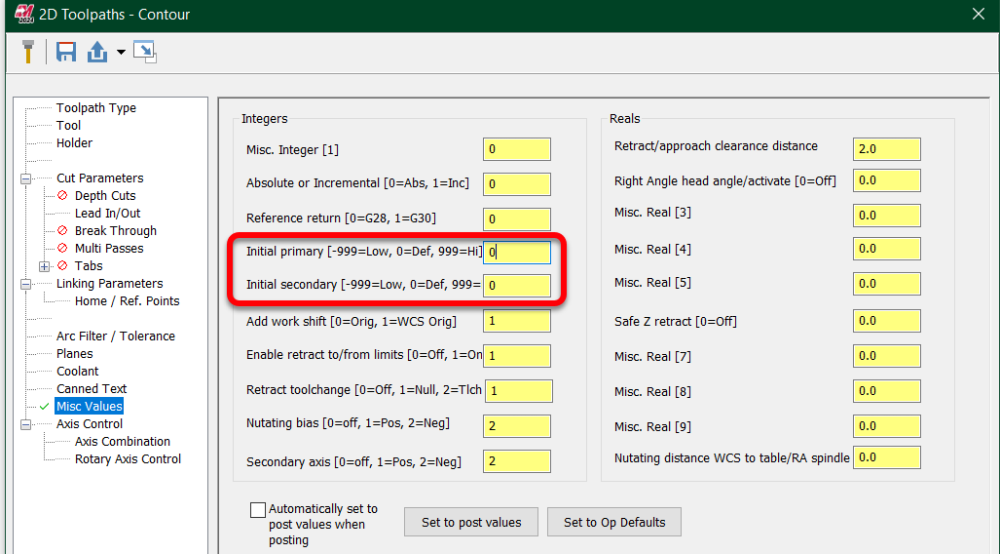
You'd edit the second op and set these to a value. What they're supposed to do is tell the post processor "start thinking about this toolpath as if the B & C are already at X degrees. In your case, you can try putting a 1 in both of them and see if that adjusts your output. It may not be hooked up correctly for your use case, though.
I've used it when I wanted it to do the opposite of whatever it was doing, i.e., it wants to go C+90, when I wanted it to go to C-270.I tried this, it didn't help in this case
On 1/25/2024 at 2:32 AM, Craig-B said:If you are using an updated copy of the Generic Fanuc 5X Mill from CNC Software, it has new switch that might help if you set it to yes$.
use_tool_plane_as_bias : no$ # Use the tool plane XY orientation as a bias when tool is vertical?
# When set to 'yes$' the operations' tool plane will be use to calculate
# the primary axis angle.
Link to Tech Exchange:
https://community.mastercam.com/TechExchange/Parts/3544#partTitleI'm using an older version of the generic 5X post so it doesn't come with this switch, I will try out this new one, it looks giving me what I want.
On 1/27/2024 at 12:59 AM, MIL-TFP-41 said:There is a switch for that in the generic 5 axis post.
frc_cinit : 1
I tried this switch, it didn't work with a null tool change, it only works when I have a real tool change.
-
Hello,
I'm working on the Fanuc 5-axis generic post to use it on an rotary table BC (C is the primary axis and B is the secondary axis).
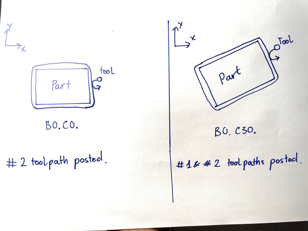
I have 2 toolpaths: #1 and #2 using the same tool:
#1 toolpath: is a 2D toolpath, takes place on a user-defined tool plane - which requires both B anc C axis to rotate (e.g. B30. C30.)
#2 toolpath: is a 2D toolpath on the Top Plane.
When I post only #2 toolpath: I get B0 & C0 output on my NC program.
But when I post both #1 & #2 toolpaths, after finished #1 toolpath on the user defined plane (e.g. B30. C30.), the tool goes back to the Top Plane for #2 toolpath. But only the B axis changes back to 0, the C axis is unchanged (still kept at C30.). So the part is no longer aligned along the X and Y axis, and the 2D contour along the edges now take place on both X and Y (instead of X or Y). That is my problem, I'm not sure if can call it a problem.
My question is: Is the any quick way, or is there a "switch" that allows us to force the primary axis to reset (C0.) if the toolpath is using Top Plane?
Thanks for reading.
-
I have the same question on the "n_tpln_mch" variable, so I tried to give it a new value = 1 right before the pg68 post block to see what happen and I got it works.
n_tpln_mch = 1
if use_clamp,
        [
        p_lock = zero
        s_lock = zero
        pbld, n$, s_slock, e$
        pbld, n$, s_plock, e$
        ]
      if stagetool <= one, pbld, n$, *t$, "M6", e$,

	  n_tpln_mch = 1
      if n_tpln_mch > m_one, #Toolplane mapping mode
        [
        #Enter your mapping scheme here...
        pg68_map
        pbld, n$, "G43", *tlngno$, *zabs_s, e$
        pbld, n$, *sg00, pwcs, "X0.", "Y0.", *zabs_s, e$
        pcan1, pbld, n$, *sgcode, *xabs_s, *yabs_s, *p_out, *s_out, strcantext, e$
        ]
      else, #5 axis and regular mode ( n_tpln_mch = -2)
        [
        if cut_ra_head & use_g45, #Swap xout and yout based on offset axis
          [
          tloffno2 = tlngno$ + g45_of_add
          pcan1, pbld, n$, *sgcode, pwcs, *sgabsinc, *yout, *p_out, *s_out,
            *speed, *spindle, pgear, strcantext, e$
          pbld, n$, "G45", *tloffno2, *xout, e$
          ]
        else,
          [
          pcan1, pbld, n$, *sgcode, pwcs, *sgabsinc, *xout, *yout, *p_out, *s_out,
            *speed, *spindle, pgear, strcantext, e$
          ]
        ]
      if stagetool = one, pbld, n$, *next_tool$, e$
Feel like it's an "open" variable so we can link it to a misc value and use as a switch to activate the "titled work plane"
This is the result code:
(3" FACE MILL|TOOL - 1|DIA. OFF. - 1|LEN. - 1| DIA. - 2.5)
(SURFACE TOP)
T1 M6
G43 H1 Z4.9013
G0 G120 X0. Y0. Z4.9013
G0 X-9.964 Y-5.5 B90. A90.
G68 X0. Y0. Z0. I0. J0. K1. R-90.
G68 X0. Y0. Z0. I0. J1. K0. R-90.
X-5.5 Y-4.9013 Z9.964 M8
G90 Z8.164
G1 Z7.864 F20.
X5.5 F80.
Y-5.9047
X-5.5
Y-6.9082
X5.5
Y-7.9117
X-5.5
G0 Z9.864
M9
G0 G28 G91 Z0.
G0 G90 G120 A0. B0.
G0 G91 G28 Y0.
M30
%
-
19 hours ago, Leon82 said:
Did you run the vector calibration?
Sometimes there are 2 or 3 calibration cycles
12 hours ago, YoDoug® said:You will need to do XY calibration as well. The macros check to see that there is calibration data. Even in a Z axis probe cycle they use the calibration for positioning adjustment for probe tip runout.
Today tried again. I run the XY calibration, and the other inspection cycles works as expected, no error anymore

You are correct, the macro need some variable for checking defined probe radius, which is get after XY calibration cycle.
-
 1
1
-
-
Thank you bros for your comments.
I will do another XY calibration to see if it can solve the issue

-
5 hours ago, nickbe10 said:
Have you been in touch with Renishaw or your reseller?
This isn't plug and play on Haas and Fanuc which it was designed around originally.
I have not, sometime it takes long to get response. I hope you had some experience with this issue.
2 hours ago, Leon82 said:Did you run the vector calibration?
Sometimes there are 2 or 3 calibration cycles
I just only run this cycle (length calibration cycle)
-
Hello,
Today I tested a Productivity plus on an Okuma.
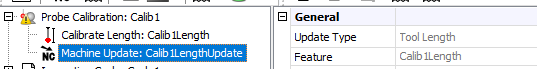
At the beginning, I called the probe and using a calibration cycle (which only use reference surface)

Anh this only calibrate the probe length.
The program running ok and I noticed the probe length was updated on the machine.
But when I made an 3-point inspection probing cycle operation for getting Z value of the zero plane, I got this error message from the machine control "REN25.INCORRECT*CALIBRATION*DATA". (Although I already done the probe length calibration)
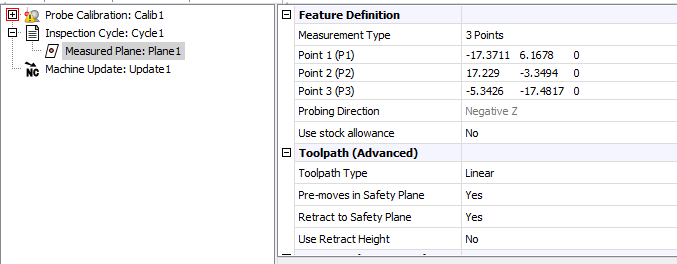
Can you help me to figure out what is the issue here? I think this is a "Z" probing operation so I just performed the calibration in Z. No XY calibration.
Do we need to calibrate XY also before we can call any inspection probing.
Thank you
-
There is an option called "Join result" which allows you to join the curves as long as the gap distance less than input value
-
Is this ftp site no longer working everyone?
-
Hello everybody,
I want to export the cut tolerance for each multiaxis toolpath to the NC file, so I'm trying to use the sparameter$ variable to capture the NCI parameter.
My problem is I have just found some parameters of other multiaxis toolpaths but still unable to find parameter for the Morph toolpath.
Hope someone can help
here are some param that I found
if prmcode$ = 10204, tol = rpar(sparameter$,1)  #Normal surface / Mport
if prmcode$ = 12376, tol = rpar(sparameter$,1)  #Msurface
if prmcode$ = 12147, tol = rpar(sparameter$,1)  #MCurve/Swaft
Thank you for reading
T.J
-
Today I tried out with:
#Offset in head based on secondary axis relative to machine base.
#Normally use the tool length for the offset in the tool direction
saxisx       : 0     #The axis offset direction?
saxisy       : 1     #The axis offset direction?
saxisz : 0 #The axis offset direction?And this works for 3+2 indexing using different tool planes.
-
I think this will help, same for 4x post
-
What are you posting? 3+2, or 5X?
5X uses the 'nutating' shift. Not 'saxisx'.
3X uses the 'saxisx' variables. 5X uses 'n_saxisx' variables.
Also, test the 'r_intersect' and 'n_r_intersect' variables. If the shifts aren't happening, enable these.
Also, the 'mr7$', 'mr8$', and 'mr9$' variables are an 'incremental shift' for tweaking an individual tool path.
Hi Colin,
I decide to do a 5X posting, also tried with the "n_saxisy", 'r_intersect' , and 'n_r_intersect' but nothing happened. Mastercam keep posting the same thing.
-
My old machine does not support these function, so I need to declare everything exactly in my post. This is where I make change in the post:
saxisx : 0 #The axis offset direction? saxisy : 1 #The axis offset direction? saxisz : 0 #The axis offset direction?
-
 1
1
-
-
Sorry, that's just a document for sharing. I have tried but it still not work. So I ask if someone can help me. Maybe I missed something in the post.
-
Hello,
I have a 5-axis table-table machine. A for X and C for Z. In my machine, the A-axis center line does not intersect with C-axis centerline (it's about 1mm offset). I've tried to edit "saxisy" value in the post but nothing change when the code generated.
I've tried on both post "Generic Haas VF-TR_Series 5X Mill" also Generic Fanuc 5X Mill"
Anyone can help me to solve my problem.
Thank you,
Giang
#Axis shift shft_misc_r : 0 #Read the axis shifts from the misc. reals #Part programmed where machine zero location is WCS origin- #Applied to spindle direction, independent of RA #Table/Table - #Offset of tables to secondary axis relative to machine base. #Tilt Head/Table - Head/Head - #Part programmed at machine zero location- #Offset in head based on secondary axis relative to machine base. #Normally use the tool length for the offset in the tool direction saxisx : 0 #The axis offset direction? saxisy : 1 #The axis offset direction? saxisz : 0 #The axis offset direction? r_intersect : 0 #Rotary axis intersect on their center of rotations #Determines if the zero point shifts relative to zero #or rotation with axis offset. #Nutating axis shift, used when calculations are based on mtype 3 or greater #'top_map' and toolplane tool paths use the axis shifts above, 5 axis use these n_saxisx : 0 #The axis offset direction? n_saxisy : 0 #The axis offset direction? n_saxisz : 0 #The axis offset direction? n_r_intrsct : 0 #Rotary axis intersection with nutating (normally zero) #Force rotary axis reset at toolchange and other options frc_cinit : 1 typ3_brk_evn : 0 #Windup limit, use even revolution break position #Primary and/or secondary brk_mv_head : 1 #Break the 5 axis moves to remove gouge brk_max_ang : 1 #'brk_mv_head' maximum angle move, applied if chordal #calculation angles moves are greater (negative disables) skp_rdnt_ck : 0 #Skip 'brk_max_ang' redundant angle check top_type : 4 #With 'top_map' select the top toolplane output #0 = Post selects G7 rotation axis #1 to 4, user selected G7 rotation axis #1 = Primary C : Y zero, Secondary A #2 = Primary C : -X zero, Secondary B #3 = Primary C : -Y zero, Secondary A #4 = Primary C : X zero, Secondary B #5 = Custom settings, ptop_type_ax and ptop_type_lim-
4
-


n_tpln_mch - what is its possible values?
in Post Processor Development Forum
Posted
again with the question: I don't know what is the actual purpose of it - aligning the plane X&Y with machine X&Y , is it just for a better visualization?