


CR
-
Posts
78 -
Joined
-
Last visited
Content Type
Profiles
Forums
Downloads
Store
eMastercam Wiki
Blogs
Gallery
Events
Posts posted by CR
-
-
"Apparently the trick is to negotiate a contract with them, if you use enough volume of products to do so. While I can't say what we pay, I can say that what we pay is usually significantly less than the ridiculous numbers they put on their website."
DITTO
next day deliverd free shipping over $100.00
-
- ditto to the Mitsubishi drills I drilled a lot of hole 0.125x40 titanium coolent thru NO peck perfec side good finish, it needs a starting hole with a short drill first then give the long drill slow rpm place it inside the hole bring the rpm up and drill it NO peck
- ditto to the Mitsubishi drills I drilled a lot of hole 0.125x40 titanium coolent thru NO peck perfec side good finish, it needs a starting hole with a short drill first then give the long drill slow rpm place it inside the hole bring the rpm up and drill it NO peck
-
"He said I have 2 back up drills invade that one breaks so I looked at them and they are too short,"
I do a lot titanium parts making holers ..carbide drills coolant thru = no headaches (as long as you have the right RPM and Feed)
Normaly I select the drill I check for length of cut (how deep is going to drill and have suficient flute length for chips evacuacion) as well as OAL, (how long is going to be extende from the tip of the holder) I place the order and give them the paper work.
ipb.global.registerReputation( 'rep_post_799114', { domLikeStripId: 'like_post_799114', app: 'forums', type: 'pid', typeid: '799114' }, parseInt('0') );
-
which brand works for you?
-
something similr happen to me once, it was machine memory capacity.
-
Mitsubishi solid carbide drill coolant thru NO peck
#MWS0770X8DB (7.7 MM DIA x 3.4 loc X 5.6 OAL
100SFM & .002 IPR
I use them a lot in titanium
the one make an imprese is 0.125 dia drill coolant thru NO peck drilling 5.00 depth
-
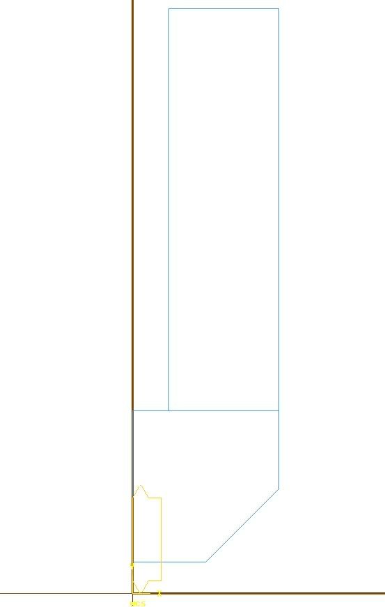
if you're doing it for the first time here are some points to remember when doing a mill custom tool
- MUST be draw only half of the tool in the TOP view X+ Y+ quadrant
- Endpoints defining the open boundary of the tool MUST BE all the way to the center line
- If you use a center line it must be dashed
- The tool MUST be a single colors
- NO duplicates, no over lapping, lines must meet center line, no short or pass center line
- MUST be draw only half of the tool in the TOP view X+ Y+ quadrant
-
ditto WCS at center of rotatation
Our
TR160 has the center of rotation at 0.128" above the face of the trunion table
-
I agree NOT peck
carbide drill thru coolant
I done b4 in a 15-5
You need to do something about the 3/4 short of flute
chips need to go somewhere
-
4 okuma Lathes We Have LB15's and LC30's
4 okuma mills MC40H's and MC3VA's
We love the them
No major broke down issues
-
Fanuc OT-B on a 4axis lathe
-
Thanks for the mail
We are getting a Haas TL25 in about 6 weeks
(main/sub/-C- axis/single turret/bar feeder)
Thank you
-
John
can this post handle main spindle/sub-spindle and -C- axis at least in the main spindle?
-
Hi Don
Having the same problem here
G0Z1.X2.6M8
Z.1
G71U0.R0.*********missing U R values
G71P21Q23U0.W0.F.008 ****missing U W values
N21G0X1.381
Also
When the G71 info is included in one single line
G0X2.05Z1.M8
Z.15
G71P11Q13U.01W.003D0.F.008******missing D value
N11G0X.7
Looks like I need to work in my X post
Thanks John
-
Good Luck
Thaks a LOT for sharing with us some of your knowledge.
God bless you and good luck to you!!!
-
What we have is basicly what John said
We use an M code in aour CNC program in our case is M181
every time the CNC program reads M181 it sends a signal to the indexer controler
the indexer receives the signal and rotate to the next step in the indexer program
It send the signal back to tell the CNC control that the rotation has been completed
then program in the machine continues.
And like Mark said
We use RS-232 port to download programs to the Haas, NSK indexers + Haas till rotary table
As for the interfacing wiring four wires are needed two for each signal (input an output)
They are from the remote input on the back of the haas control (male 4 pin DIN connector)and from your CNC machine (I recomend to hire samebody the knows how to do it)
-
Done
Thank you!!!!
-
quote:i set value manual in parameter or by MDI through G10 P1 x...y...z...
Do not forget the Q2

G10Q2P.....
-
Ken
To input the fixture offsets
Switch to MDI
then use the following command
G10Q2P(value)X(value)Y(value)Z(value)A(value)
(REF. G10Q2P1X-5.276Y-7.485Z-8.010A0.0)
G54=P1
G55=P2
G56=p3
G57=P4
G58=P5
G59=P6
A= 4th axis
as a remender
When you use cutter com.need to use the
D41 and up offset.
Ref. G01G41X-.025D41(D41 TOOL RADIUS)
Hope these help
we have the same amchine, same control
-
Same as stated above...
-
Jason
I upload a file with a thread cycle in th ftp site
Lathe/threading.mc9
It has a thread custom tool.
Saved it in your tools directory
-
-
he way I do it
I created a custom tool with the face of the insert at Z0
Suggustion on drawing the tool:
- Select the holder with a thread insert that has (roughly) the same dims as the tool you will be using. Click on 'Draw Tool' and select 'File Save' from the screen menu.
- Traslate the holder and insert so the insert face is at Z0 and the tip of the insert is at X0 (mod. the tip radius if needed) and use the result as the .MC9 file that your custom tool is based on.
Lathe custom tool geometry rules:
There must be separate planar closed boundaries for the insert and holder drawn in the Top view.
The boundaries must consist of lines and arcs only.
The insert and holder geometry must be different colors.
There must be no other geometry in the file.
Endpoints of entities defining the outer boundary of the insert and holder must be within .00000005, or you may get error messages
It work for me
We also get the "Z" offset from the face of the insert
Hope this help
-
Hi Felix
Use a thread insert with a 0.010R +/- .001
Like kennametal # NTC3R12E this will give you the right minor dia
If you want the one for the "J" thd it will be
Kennametal # NJP3014R12 (.0125/.0135 R)

STL file creation
in Industrial Forum
Posted
Run verify and save the SLT
if you going to used that STL for a 2nd op
Open the STL file as stand-alone not inside another Mcam file
make sure to open it with the option "import as STL mesh"
rotate / translate as necessary for your next operation
re-save as "STL" again
open you file for the 2nd op and reference your re-saved STL