


Shoggoth_2150
-
Posts
22 -
Joined
-
Last visited
Content Type
Profiles
Forums
Downloads
Store
eMastercam Wiki
Blogs
Gallery
Events
Posts posted by Shoggoth_2150
-
-
57 minutes ago, cncappsjames said:
On the filter tab you have arc/line tolerance options...
Depending on the geometry of the feature(s) you could do a 2D/3D Swept path plus you still get filtering options as well.
There is only 'Tool Filter' under the Flowline tabs. Not that I can see in 2020.
-
Just curious if anyone knows a good way to reduce the size of the post when using 3D toolpaths. Flowline specifically. When doing 2D/2.5D units there is the Arc Filter Tolerance you can use to drastically reduce the size of the code being spit out. Is there a way to do similar in the 3D units?
Under 'Finish Flowline Parameters' tab, the 'Cut Control' box. There are the 2 options for 'Distance' and 'Total Tolerance'; will increasing these values reduce program size, and what adverse effects do they have?
If anyone has some tips for reducing the size of the file, other than increasing stepover, I'd love to hear them.
Thanks.
-
15 hours ago, gcode said:
Both John and Ron are correct
If your IT Department has your Public folders locked down you will pound your head against a wall till the end of time
Yeah. It's frustrating to have the computer lock up for a minute every time you do something, only to end up with an error warning and no explanation of what the problem is. I'm no IT guy. Having it looked at today.
-
Oh I'm not the first person to vent on here. I find MAZAtrol so simple and intuitive. The fact that there are about 10 times more fields to fill out in Lathe than the Mill boggles my mind. Everything I've done as far as classes and education have always been very focused on geometry creation and toolpaths. Never have the nuts and bolts of the program been addressed. Material Library, Tool library, Altering tools and changing Control and Machine definitions; these things are all a lot harder to find info on, or people that can explain well. I do openly admit my bias, being in a job shop. If I was back in aerospace doing long run jobs, I could see the benefits. Easy to swap in new tools and make alterations to paths for efficiency. But for MY needs, it's not the best option. Still want to get a handle on the things that trouble me though, so thanks for the tips. Much appreciated.
-
16 minutes ago, JoshC said:
if you hate Mastercam lathe then its likely just a lack of training on your end, I would encourage you to check out the Free online lathe courses being offered here https://signup.mastercam.com/free-mastercam-training
Once you sign up you can login and view the lathe training courses here https://university.mastercam.com/
and a step up from that would be a lathe course at a local mastercam reseller.
I hope this helps.
I've done years worth of training on it. Every level in college and every course available through the sites. The problem is, it just stinks. I've been cutting metal for 25 years, and anywhere I've worked, MC Lathe is an absolute last resort. Probably use it only once or twice a year. Compared to MAZATROL it's like rocket science. So when I absolutely am forced to use it, I either remember nothing, or it's been changed for a new version. I can see benefits for long term production, but in a Job Shop where you just need to kick out a few parts, it's really useless. Spend 5 times as long programming as cutting. Just my time tested opinion of it. But you are correct, I don't know nearly as much as I should, since I avoid it like the plague.
-
So I'm trying real hard to wrap my head around Lathe Tools in Mastercam, with no luck. Here's a file. I copied unit 5, made a unit 6 and tried creating a tool with a .075 width for the 4th pocket. Works just fine in unit 5 (but the blade is too wide), can't get it to do a thing in unit 6 with the tool I made. Seems like it's set up right, and it draws fine. If anyone can point out what I did wrong, or didn't do at all, I'd love some pointers. Have I said how much I hate Mastercam Lathe?
-
I guess a big part of my problem is this warning. Pops up every time I try to change something on whatever tool I select. Won't let me rotate the angle for plunging, etc. Anybody know what it's all about? Stays default and ignores any changes I try to make.
.png.6236766ef27f9b40fa8407be8eec59c3.png)
-
4 minutes ago, JParis said:
There was so much wrong with that I am not even sure if I am representing your cut as you wish it...
I urge you to look at how the insert projection on the holder tab now has the tool at .75 projection and not the same .500 value that is shown to the holder block size
I used the stock radio box to allow it to use the stock boundary and then had to the set the Lead In/Lead out directions..
I am only guessing that this is what you were trying to get
Yeah, that's what I'm after. Not going to be the tool I use, but I guess as long as the insert is the right way the tool doesn't matter much. It's what I want to do, but no understanding of how you got there. Can you change the insert orientation on any of the bars that are in the MC library, or do I have to hunt the internet and download a Face Grooving Boring bar w/ insert? As I said, I tried to make one but it has the orientation all wrong. I worry the code will be all messed up if I don't have a tool that's at least close to what I'll be using.
-
12 minutes ago, #Rekd™ said:
Your tool is not defined properly. Go into Setup tool and set the plunge parameters to 180. Then use the Draw Tool command to see if it is correct.
The holder dimension is not correct either, you have D and A the same dimension.
Draw just puts the tool backwards when I do that. No matter what I change, the insert is still in the Up/Down orientation with the shank embedded in the part.. Get a nice warning now about shared tool files as well. Is there no face grooving boring bars to be found in Mastercam anywhere? I shouldn't have to be trying to cheat an OD tool for such a simple task, should I?
-
First let me say, I hate Mastecam Lathe and rarely use it. I'd much rather spit out a MAZAROL program because it's so much easier. That being said, not everything can go on a MAZAK, so I have no choice but to fight with Mastercam. I hate how you have to draw out geometry for every step of every operation. I've done so many of the training tutorials, but none have ever helped out with the basics. The problem I'm having now is trying to set up a tool for face grooving. I select the face grooving option in the GROOVE unit, and it supposedly puts the tool in the right orientation, but whenever I backplot or try to regen the toolpath, it has the tool in the orientation for the OD, and the first thing I get is the warning that my tool is embedded in the part. WTF??? Nothing changes the orientation that I can find. And when you try to create a boring bar, it puts it in that upright orientation as well. Tool orientation is a mystery. Having the tool set the right way seems pretty important. Mastercam Lathe sucks. Why's it got to be so hard and convoluted. I can whip up 4 and 5-axis toolpaths for days on the mills, but 2 axis lathe is all but impossible to get working. Can't get it to do anything outside the box. Any hints, tips, or tricks would be welcome. File attached.
-
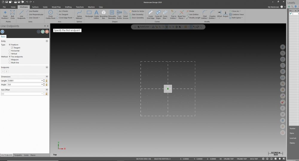
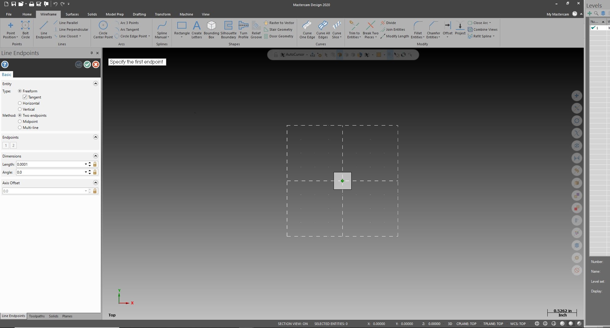
Shut the system down and rebooted, now the box is back to normal size. I'd still like to know how I changed it in the first place. If you know, feel free to chime in.
-
Hey all. Quick question for those that might know. I don't know why, but today while using mastercam, my selection pick box grew to 20x it's original size. I didn't even know it could be changed. Any time I go to make a selection, the massive white box makes thing difficult to see where you're at and what it's snapping to. Anyone know how to change the size of the box? Kinda driving me crazy and I can't find how to adjust it.
-
14 minutes ago, JoshC said:
Do you have a multi-axis license? Also are you looking to rough this part with the A-axis rotating during the cut or are you doing it 3+1 and locking the axis?
it looks like it could be roughed like you are setting it up with 3+1 and just Positioning the 4th axis or could be done with a simultaneous multi-axis path. Also what kind of cutting strategy are you looking for because if its a softer material flow 5 axis would be super easy to apply and we could zigzag, or if its a harder material we could Peel Mill with axis substitution to climb mill only. You have many options but luckily this part is an easy one to learn on, let me know your thoughts on those questions and i can provide some examples once i get a better idea of how you would like to cut it
Do have multi-axis. Sounds like what you say about peel milling is exactly what I want to do. It's alloy steel, somewhere between 4130 and 4145. Not too hard.
-
8 minutes ago, jwvt88 said:
Multiaxis roughing is perfect for this application if you're using 5 axis.
Don't have a 5 big enough. Going to be on a 3 + A-axis.
-
I'm completely lost on how to accomplish what I'm trying to do. I will openly admit I have no idea what to do for this one. I want to rough and finish the area between the wings on this part, and have not been able to come anywhere close to getting it right. Nothing I've tried will work. I've tried with and without the rotary, and several different toolpaths. Could anyone point out what I need to do to make this work.
Ideally I'd like to do Dynamic milling up one side of a wing, starting from the wide open space on the left, then have it rotate through the middle to remove the bulk of the material, then finish up on the opposite wing. Then from there do whatever finishing I need to. I just have no idea how to get it to hog out the bulk of the material. Everything I've tried is garbage. Please help if you know how to go about this one.
I've attached the .mcam (2020) file. Thanks.
.thumb.png.4366777cce161ce4bd0b50f1257b6af0.png)
-
It all worked out for me, except for one odd issue. On the computer it was climb milling, on the machine it was conventional. Any ideas why that would be?
-
6 minutes ago, huskermcdoogle said:
I didn't see it that way... I think he wants to use the rotary.
Instead of chaining a flat arc, you need to chain the intersection (solid geo) then check unroll geometry with a tight tolerance in the operation axis sub parameters. Doing it this way gives a much finer motion for the axis sub. Otherwise, the way you had it, will default to the tolerances in the post I think to break up the arc into an axis sub situation. With my method its all point to point and the post will only map the coordinates, it won't be breaking it up. Mind you, you should be close to tangent on the top edge, but the inside won't be tangent. No way to get both with that tool. if you want a good tangent fillet, you will want to use a ball end and surface it.
This is exactly what I was looking for. Thanks. When I was playing with UNROLL it put the toolpath out in space. Didn't think it was the right setting to make it work, so I didn't bother toying with it much. Tightening it up really helped. Now I know. Thanks.
-
 2
2
-
-
I'm trying to do something very simple and getting nowhere. I want to put a constant radius on the edge of a hole that goes through a piece of round stock. I've done things like this with 3D models, but can't find a solution with this simple sketch up. Should just be able to sub the Y axis and get what I want, but it isn't cutting a smooth line. Instead it appears to be piecing together a bunch of straight lines instead of arcs, and it looks like junk. How can I get a smooth rad on that edge?? Do I have some settings wrong? Any help welcome. File attached.
-
33 minutes ago, cncappsjames said:
You must not be in the US @Shoggoth_2150. CAMplete Comes with the Matsuura 5-Axis machine purchase in the US. The only charge comes after the 1st year. Maintenance... and it runs around $1,500 per year.
If something "costs" $18k but it works right out of the box and in a couple hours you are ready to go at the machine, it requires no back and forth for a month to get things right, collision checks g-code in your actual machine, or, something else "costs" only $3,500 yet is going to require a crap ton of effort, time, and you never really know exactly what you are going to get out at the machine which one "costs" more?
Money you can make back. Time, once it's gone, you can never get it back.

Nope, in Alberta. The machine was part of an acquisition, and the licence had expired. I should clarify, however, that $18k price tag was for 2 machines, the Matsuura MX-520, and a Nakamora Tome WT-300. We'd have needed both versions of CAMplete, True Path & Mill Turn. The Mastercam posts for both machines was 1/3rd of the cost, and we already use Mastercam for every other machine we have. It was a matter of cost and standardization. Only thing lacking is not having full simulation out of the gate. Still making parts on them no problem.
-
2
-
-
It was $18k for CAMplete, versus $3.5k for a Mastercam post. We priced it out. Money talks...
-
 1
1
-
-
So while I'm not new to Mastercam, there are things I've never been able to find good answers to, or resources for. For instance:
-How do you add to or create/update your Materials Library? Half of the Metals we cut aren't in the default library and I've no idea how to expand on it to include new materials. I usually just end up picking a metal as close as I can find to what's being cut.
-How do you create a new Tool Library? I often download tool models from MachiningCloud and want to make Libraries according to manufacturer. I know how to add them in by the job, importing them one by one, but no idea how to create a fresh Library so I can pull them whenever I want.
-Is there a way to add in machines to the simulator? Is there some resource somewhere that would allow you to download a 3D version of the machine you're using in the real world to show in the simulator? I'd love to add my 5-Axis Matsuura MX-520 into it so I could actually see any collisions happening.
As I said, I've never been able to find good answers to these questions. It's one area of my Mastercam knowledge that has always been lacking. Any information that anyone has to pass along, or resources, would be appreciated. Perhaps there is some corner of eMastercam that explains it all and I just haven't found it.
Thanks.
.png.5cd2997e232a3e6345114a10e218d923.png)
Flowline Post Size
in Industrial Forum
Posted
Third Tab on my 2020. 'Total Tolerance' button. Cool. Thank you. I didn't know about it. Should help out!