


Panda_Guy
-
Posts
15 -
Joined
-
Last visited
Content Type
Profiles
Forums
Downloads
Store
eMastercam Wiki
Blogs
Gallery
Events
Posts posted by Panda_Guy
-
-
Analyze Dynamic reports the "Current Color" of a solid face that has been changed from the original solid color.
In Mastercam 2017 selection is enabled in the "Selection Bar" .
Mouse over the cube with the green check mark. Click it and then you toggle edge, face and/or body options. (Most times you can select more than one, depends what you are doing.)
-
I put it in the same category of NURBS interpolation.
Seemed like it was going to be the next big thing, then....
-
...
G91 G01 Z-1.0 F100.0
G00 Z1.0
M99
...^fixed it for you
-
 1
1
-
-
We use exclusively wear for radius compensation, so the path is offset by MCam and we just make small adjustments at the machine as needed.
Not familiar with your control and its preferred methods, so nothing to offer there.
On Fanuc compatible controls, you have to be careful not to turn comp on or off with an arc move as it will throw an alarm.
A few years ago, there was a self proclaimed "Best Programmer" here. 3 of us were working on a Sunday, which meant he divided his time asking the other two of us how to do his job. He asked me what "Comp in Control" meant. My answer was, "I forget. I never use it or "Comp in Computer" for that matter, so I tend to get them mixed up."
He replied, "Well I just tried it and it scrapped my part." His part was a huge billet of customer provided material. Nice place to try something you don't understand, eh? We never saw him again.
-
1
-
-
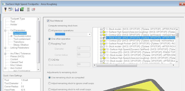
When using surface restmill operations, you can use it for "rest material" as "one operation".
-
I came to pose the same question. Glad I searched before asking.
The checkbox in Plane Manager helps, but it now displays the C plane and T plane as Undefined*, which I don't like. What was wrong with the way it was?
-
You didn't mention if they are HSS or Carbide fluted.
Either way, we usually run them with surface footage appropriate for a reamer of whatever material they are. In other words, low. They tend to have a lot of contact at the end of the stroke.
Another trick you may want to explore is to define them as custom tools and draw up their shape and put the spotface at "Z zero", since the spotface has to clean up to create the correct form and radii, etc. Just be careful with your initial planes so the pilot diameter doesn't hit in rapid.
-
When I first started using Mastercam, the company I work for had just hired another programmer who had been using it for years. Our manager wanted us to standardize our methods so what was hitting the shop floor was consistent regardless of who programmed it. One of my requests was comments on every tool and every operation. The other guy said, "That seems like a lot of typing. If the set up guys want comments, they can add them." I couldn't believe he was serious, but that was how he was used to working. His programs were basically a black box and if anybody needed a simple tweak, they had to go to him for it. I feel a lot better if the guy executing the code is aware of what I am trying to do.
-
1
-
-
^ this.
We actually use them for surface toolpaths on a couple of titanium jobs with success. Defining them as bullnose would not work well for that.
In the case where the manufacturer does not make the CAD drawings or complete dimensional info available, we have made measurements of angles, tangent points, etc. from our tool presetter.
-
The translators actually have come a long way since I started with MC (V9). It surprises me that you are getting IGES files for an aerospace part. Is it a legacy part?
Most of our aerospace files come in STEP or X_T, almost never IGES.
When we do have trouble translating it is due to a bad file or something the customer did when converting it.
-
No bug, it's a Win7 thing
Thanks, John, but why do I only see it in Mastercam? Other apps, such as Cimco editor, seem to work fine.
By the way, Excel does this in both OS.
Does anyone know a fix within Win7 or does this mean I have to start paying attention?
-
I recently migrated to a new PC at work. I run X6 MU1 (64 bit)in Win 7. My previous box was XP pro. On the new box, when I double click in a numeric field, the digits and decimal point are selected, but if present the minus sign is not.
As an example, if adrill depth is -.5 and I want to change it to -.6, and I double click that field and type in -.6, it becomes --.6 which of course is .6! It may seem like a small thing, but that has been my SOP for many years and I am getting too old to have to pay that close of attention to something that routine.
I searched through the settings looking for a box to check/uncheck, but came up empty. At first I thought it was a Windows thing, but it only happens in Mastercam. Another programmer with Win 7 has the same issue, but it was his habit to drag to cursor to select.
Anybody else out there seen this and found a fix?
-
Yes, and thanks in advance for the X6 work. My chief complaint with X6 is lack of your setup and tool lists.
-
Back in version 9, when you backplotted with the color cycle option activated, whether by tool or by operation, each path was drawn in a different color. Ever since X came out everything is drawn in the same color regardless of what is checked in backplot display options. Does it have to be enabled somewhere else? I found it pretty useful once I stumbled across it in V9.

-------------------
X2 SP1
MILL LEVEL 3
SOLIDS
5 AXIS VERIFY
Can't select edges, only surfaces.
in Industrial Forum
Posted
Sounds like you are missing wireframe geometry. You stated you are working with a surface model. I assume you mean it has no solids, just surfaces.
AFIK, surface edges can't be selected like edges of a solid, so if you had been doing 2d tool paths up to this point the wireframe entities are either in a level that is not visible or they are blanked out.
Select edge won't typically work on wireframe geo, so if your screen is populated by only surfaces and wireframe geometry, it would be grayed out.
Hope this helps.