


bensls
-
Posts
17 -
Joined
-
Last visited
Content Type
Profiles
Forums
Downloads
Store
eMastercam Wiki
Blogs
Gallery
Events
Posts posted by bensls
-
-
It is unchecked everywhere.
-
It's doing it for all posts and all machine / control definitions.
How is it even possible that changing a setting in one control definition affects all of the definitions in my mcam folder? Not only that, but they all show that the setting is back to normal.
-
I'm having an issue with this as well. I followed all these steps but it's still posting the adjusted feed rate on arc moves. When I go into the machine def and control def, it shows the "Adjust feedrate on arc moves" box is unchecked. It is also unchecked in the Tool Settings tab. Any ideas?
-
In X9, the Simulator view was controlled by the workspace WCS. If you were in your custom "Sequence 30" WCS plane, then using Alt+7 in the Simulator would show an Isometric view of that plane. In 2017, all the views are with respect to the default "Top" WCS regardless of which plane you are working in, so you can't see an Isometric (or any other) view of a custom plane.
Am I missing something that allows you to enable the old functionality?
-
The arcs sort fine. The points do not.
Unless that is a new feature in 2017. I'm running X9.
-
Haas also has a subroutine command (M97) that makes it really easy to do things like this. Instead of having 8 different copies of the same operation for each angle, you can do something like this:
G0 G17 G40 G49 G80 G90
( 0.125 CHAMFER MILL )
T1 M6
G0 G54 G90 X.0625 Y0. A0 S6000 M3
G43 H1 Z.1
M8
M97P1000L8M9
M5
G28 G91 Z0.
G0 G53 G90 Y0.
M30N1000
G90 X.0625
G1 Z-.03 F30.
X0.
X-1.4313
X-1.4938
G0 Z.1G91 A45.
M99
So it makes the cut, rotates 45deg incrementally, then repeats a number "L" times. Don't forget to check your G90/G91 commands though. That would make a mess.
-
 2
2
-
-
It's a formula that some one figured out a long time ago. The only thing Jeff forgot was a 135 degree sweep for angle . So for a .737 hole using a 3/8 endmill it's .737-.375 =.362 / 2 = .181*.4142 = .0749702. That is your lead in lead out for line and arc with a 135 sweep you will always go to center of a hole. Also handy for slots and a few other things where your sweep is tight. A little math for a 45 and you can bang it right on center or at least within a minuscule amount that your operators should be comfortable.
Ah okay. That's what I meant earlier when I said it could be figured out with some trigonometry. I should have known someone had already done the math and made it into a simple equation. Thanks for clearing that up. I'll definitely keep that constant handy.
-
If I recall correctly the order doesn't matter. Hit the enter/exit at point and let it go.
Tried that already. It's a mess. The entry points just don't coincide with their respective circles.
Yes you are, a simple equation will put your tool right on center of the hole when selecting just the circles.
(hole size - tool diameter /2) x .4142
Well, I don't know where ".4142" comes from or where you want me to put that information. But I could use the equation (hole size - tool diameter) / 2 if I were just using an entry line with no arc. But I want to use an arc.
Or circle mill will put it directly on center, and if it's a 90 deg chamfer tool, then the math is easy also.
That's what I've been using as a workaround.
But afaik it's not possible to sort the points like you're asking unless I'm totally misunderstanding your question.
That is exactly what I'm asking. So I'll just assume we've reached a consensus that it is not possible to sort contour entry points and I'll continue using circle mill instead.
-
You are just over thinking it
No, I'm not. There is a perfectly reasonable explanation for wanting my tool to move to the nominal hole location before each chamfer operation.
It is possible to do this, but it involves placing the entry point before the contour chain in the chain manager. I simply would like to know if it's possible to link these geometries so they sort correctly, or if it's possible to sort contour entry points at all.
-
Entering in the center for chamfering a hole is no big deal...just use your Lead In/Lead out to create a safe distance....
Yeah I'm not worried about plunging into the part or anything. Using Lead In/Out, you can get really close to the center of the hole with trial and error (or you can get virtually right on center if you want to do some fairly involved trigonometry to figure out the lead in arc length combined with the lead in line) but it's still not the same as simply using an entry point to locate directly at the nominal hole location.
My question is more about sorting linked geometry in the chain manager.
-
Are the circles all different sizes?
I never select the point AND the circle, just the circle for my 2D chamfers.
The circles are all the same size in this case. If you don't select the point, the toolpath will start at the beginning of the lead in line. I want the toolpath to start at the center of the circle.
-
I have a lot of holes that I need to chamfer, and I like to use the center of holes as entry / exit points so the NC code moves the tool to the nominal location of each hole before plunging and circular interpolating.
Normally, I would just select the center point of a hole and then select the circle. Then I'd check "use entry point" and "use exit point" under the Lead In/Out parameters.
The problem I'm having is that the points in the chain manager don't sort along with the circles, and I don't have time to (and really don't want to) manually move each point before its associated circle.
Is there any way around this?
I know I can just use a circle mill, but then I have to figure out the correct depth and negative wall stock. Not the end of the world, but also not as simple as using the contour chamfer function. Also, I wouldn't be able to specify my Lead In/Out line and arc.
I can also just abandon the entry / exit points altogether, but I like to see (and want my operators to see) the nominal hole locations in the NC code as a quick check to make sure they're all in the correct location.
-
- Popular Post
- Popular Post
If you want to know the distance between a point on your toolpath and any solids / geometry, go into Toolpath Editor for that operation then do an Analyze Distance. Mastercam lets you select points along the toolpath when you are in this mode. You can skip posting the operation and/or doing the math.
-
10
-
with CDC??
that violates everything I ever learned about CDC
If you're using Control compensation (entering the radius of the tool into the machine control), you might not want to use tangent lines to avoid large comp moves while entering a cut.
But I use Wear compensation almost exclusively, so tangent lines wouldn't make the cutter move a significant amount before the cut.
-
Another thing to check (that I really hope you are not doing) is if filter turned on.
Ugh. It was actually the "Smoothing Settings" checkbox that did the trick. It still works with filtering (not that it's necessary for a straight line) as long as that box isn't checked. Thanks.
Looks to me like garbage in, garbage out.
Very helpful. God forbid I need to use something as basic as a tangent lead in/out.
I see what the OP is saying... Ignore the finer points of cutter comp, and look at the output.
Mastercam should be outputting 3 elements; A lead in, a move along the chained geometry, and finally a lead out.
Even if all 3 are parallel, it should output them all separately. I personally use tangent lead's with no sweep all the time and it works for me(X9).
This is exactly what I was getting at, but I can see why having the smoothing settings turned on would affect the tangent lead out like that.
To all others, thanks for your input. I generally do use a perpendicular entry/exit where the filtering settings wouldn't affect cutter comp output. But for those instances where I need to use a tangent entry/exit, it's good to know where this problem was stemming from.
-
1
-
-
- Popular Post
- Popular Post
I've been having a problem with cutter comp recently. I updated to X9 a few months ago and I don't remember seeing this before the update. I don't think I would have missed this in the NC (or when checking my parts).
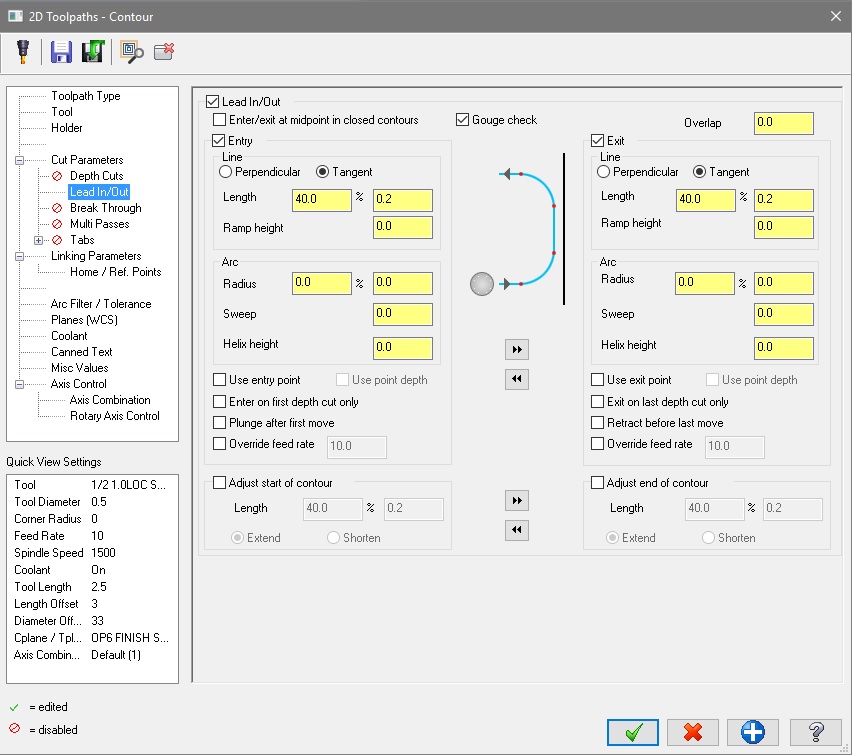
Basically, on contours with a single straight line, the toolpath combines the line geometry and the Lead Out. So an example of the code looks like this:
T3M6G49G0G90G57X3.492Y.3182M8G43H3Z.1S1500M3Z.05G1Z-.95F20.G41D33X3.6335Y.1768F10.G40X4.1568Y-.3465G0Z.1Notice there is no move between G41 and G40 where the actual line is.I attached two pictures. The first shows the backplot of the path. You can see the Lead In as the blue part of the line, but the red part of the line shows both the geometry move and the Lead Out as one step. The second picture shows my Lead In/Out page. Nothing fancy. Just a straight line.Sometimes I can change some parameters that shouldn't affect this at all, and it will fix the problem. Some examples:Change the plunge and feed rates so they are not the same.Un-check "Enter/exit at midpoint in closed contours".But sometimes those strategies don't help.I have tried using the "Adjust start/end of contour" option instead of Entry and Exit to no avail. I've checked my Configuration and Control Definition to no avail.It's not a problem with the post because I used three different machine posts and they all output the same code problem.Right now I'm stuck manually editing the NC or modifying my geometry. Any help on the issue would be appreciated. I'm probably missing something painfully obvious.
-
10

Turning off adjust feed on arc move?
in Industrial Forum
Posted
Well, it turns out I just had to regenerate the toolpath. Now all of my programs are back to normal.