


buckrich81
-
Posts
9 -
Joined
-
Last visited
Content Type
Profiles
Forums
Downloads
Store
eMastercam Wiki
Blogs
Gallery
Events
Posts posted by buckrich81
-
-
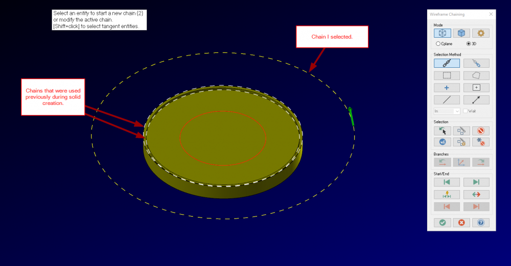
I am rolling out 2020 shopwide this month and I have noticed an issue. Every time I select a chain for solid modeling or toolpathing there are other chains that are highlighted in the graphics screen. It is always the last few chains selected, like it is a 'ghost' or a remnant from a previous operation. This does not affect the functionality of the software it is just annoying. I was wondering if anyone else has experienced this or has a way to make it stop. Here is a screen shot of a simple 'dummy' example.
-
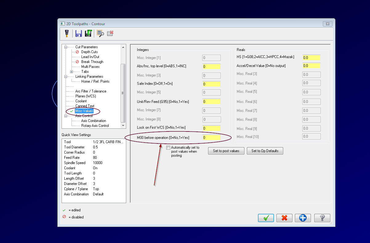
I commonly add an M00 after an operation. In the Misc Values page there is an option to add an M00 before operation. I simply toggle this to yes at the operation AFTER the desired M00 location. This will add the M00 with a G53 Z0. Y0. between ops. Add in a Manual Entry toolpath and you can accomplish exactly what you are asking for.
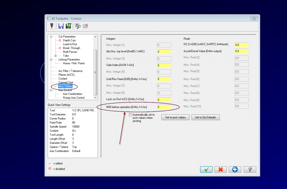
Now perhaps this is something that exists on our post. But with a manual entry any combination to G code, M code and comment can be added to any desired location.
-
 1
1
-
-
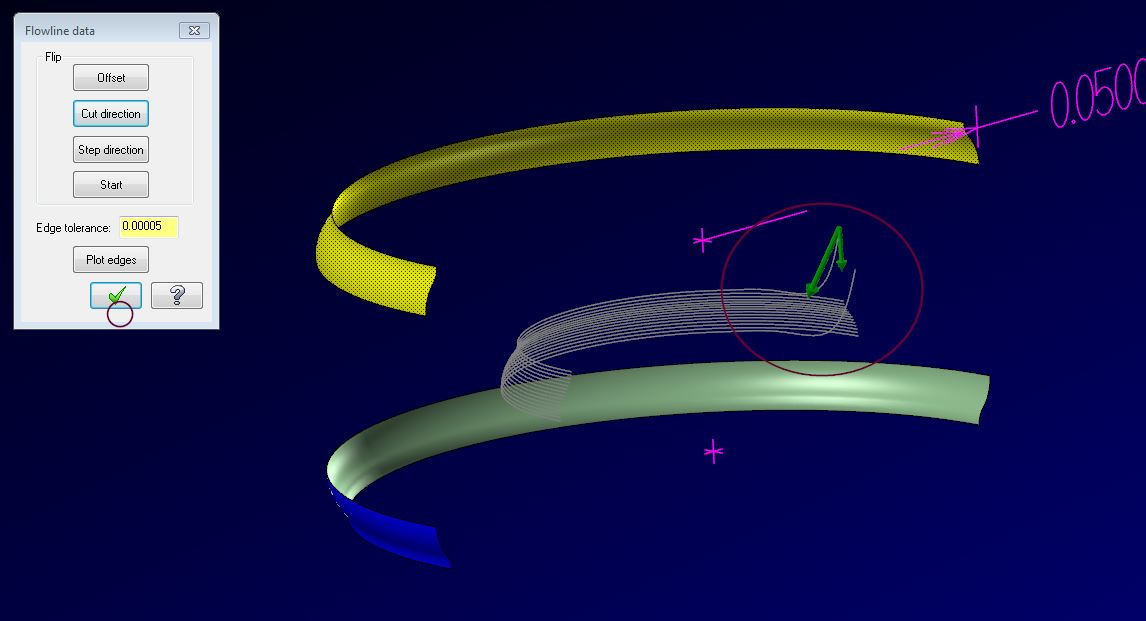
The problem is not the parameters in the direction dialogue box, it is the nature of the surface being used. The file I looked at was made of trimmed nurb surfaces. When I opened the flowline data parameter for the surfaces being used it was plain as day that the surface had some irregularities that was causing the lead-out to crash through the part.
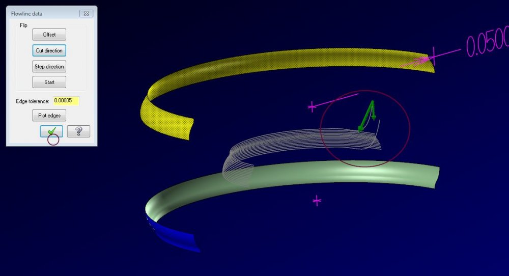
I made a solid using the geometry available and then attached the tool path to this new surface and then re-gen. Problem solved.
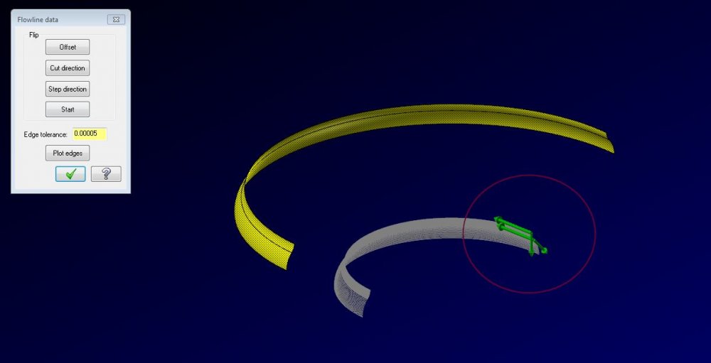
Hope that helps.
-
2
-
-
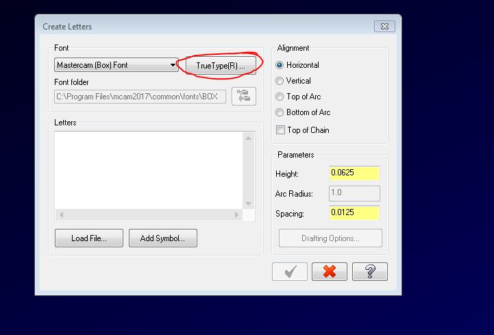
You can use any font that is in Windows. Simply download the font needed and add it to the fonts folder in Windows. If you have Windows 10, simply right click on the font file and tell it to install. If you are using Windows 7 I believe you have to add it the fonts folder, (Google should know how to do that.
.gif ":)") ). After the font needed is added to Windows you can select it as a TrueType font while creating letters. I hope this helps.
). After the font needed is added to Windows you can select it as a TrueType font while creating letters. I hope this helps.
-
On 10/22/2017 at 1:47 AM, David Colin said:
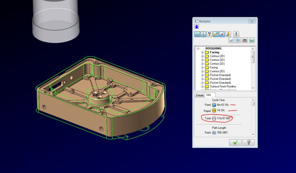
About erratic backplot times, it looks like Mastercam adds tool change time, using what is set in MD's tool changer component. In a certain way at least... if you put in 0 second in that field, total time should be OK (sum of feeds+rapids). Still inaccurate though as Mastercam isn't kinematic aware.
Thank you David. I really appreciate the response with a direct answer to my question. I have made the change and the numbers are back where they should be.
-
11 minutes ago, gcode said:
have you tried running it through Verify?
It also reports cycle times.. though I don't know if they are more or less accurate than
Backplot cycle times
I must have did something wrong during my install. I have not used verify since Machine Simulator came out, I believe it was X7, and just now when I attempted set it up Mastercam crashed. I tried it 3 times and it crashed all three. Thank you for the suggestion. I am now on a mission to find out why verify is not working for me, and then I will attempt to compare cycle times between backplot and verify.
-
18 minutes ago, C^Millman said:
Yes I have seen this and reported it.
More noise might get this issue resolved quicker. Thanks for the reply.
-
Has anyone else noticed that the estimated backplot times in 2018 are haywire? I know that the backplot times have never been "accurate" at all in any previous version, but at my shop we use the backplot time with a certain formula dependent on which cell system the part will run on to determine a preliminary "estimated" run time. This has been fairly accurate for me in past versions. In 2018 however the math on the info tab while running backplot is WAY off.
Anyone else dealing with this bug? Looking for suggestions as to why or any other insight.


Highlighted Geometry Issue With 2020
in Industrial Forum
Posted
That was it. Thank you for the help LeoC.