


Router_Skelter
-
Posts
8 -
Joined
-
Last visited
Content Type
Profiles
Forums
Downloads
Store
eMastercam Wiki
Blogs
Gallery
Events
Posts posted by Router_Skelter
-
-
1 hour ago, Rstewart said:
Great Video!
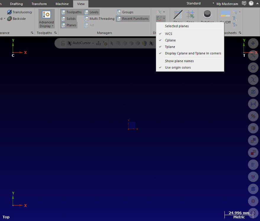
Slightly off topic, but what setting keeps the X,Y,Z Gnome visible at all times. Somehow I've gotten mine configured where you have to hover over it for it to be visible. This is even after I toggle that X,Y,Z gnome button in the planes manager.
Seems like I have tried every damn setting lol, 2021 wasn't like this.
-
You can also adjust the precision factor in the simulator defaults.
-
What thermwood model are you having these problems with? We are about to scrap two oid 67s, not fast enough in my opinion. Our rule of thumb with them is only use raster, waterline and horizontal toolpaths otherwise its gonna be a bad day. Also what type of work are you doing? Using their macros over inputting tan and acc values?
-
 1
1
-
-
Sorry it's taken so long to get back, I got slammed but thank you Ajmer I would never have thought to look at the extend to infinity as I don't really understand it, generally just turn collision control off and sort it through verify and adjusting toolpaths. Being routers more 3+2 than full 5 axis. I cleaned the weird move up, not perfect but much nicer can share that next week if people are interested
-
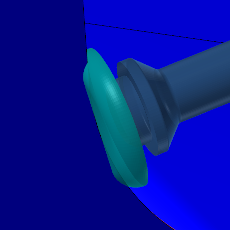
Thank you for the advice guys, so far i have tried using a standard bull, flat and barrel tool definition. Tried run tool auto and at radius. Tried offsetting a surface, making it drive and the tool face check geo all with no luck. The other thing i`ve found is when making a triangular mesh rough toolpath setting the tool axis control to from chain the only tool that will tilt as it`s ment to is a ball, endmills stay in 3 axis.
-
I had no luck with that.
-
Hi Guys,
I`m having problems with Mastercam not compensating for the tool diameter in a morph toolpath. I would generally program the part with a ball which works easily, but this time need to use a large bull style cutter as the parts are over 9.5m long. I`ve included a simplified sample file with a small section of the part, i can program it 3+2 but was hoping to do it multi and hoping its just something simple im overlooking. Any help would be greatly appreciated.
How do you "remove/keep chips" while in Machine Simulation?
in Industrial Forum
Posted
Inside the measure tab in machine sim is what i think you are looking for