


ANESIMIN
-
Posts
29 -
Joined
-
Last visited
Content Type
Profiles
Forums
Downloads
Store
eMastercam Wiki
Blogs
Gallery
Events
Posts posted by ANESIMIN
-
-
hI
I am using cimco edit 2023 and i notice a new tool position display.
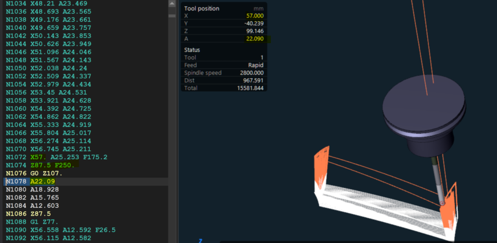
the problem is i am running a 4 axis program with no motion along Y axis. it must be always at 0.
i only have correct position for x axis and A axis .Y and Z value dont match the program positions.
is it possible to modify tool position display according to program origin? and have correct tool position ?
Thanks for you help
-
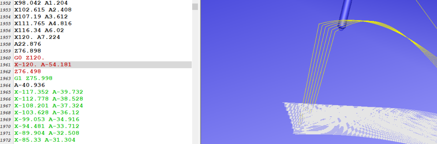
Please have a look at the rapid move when using 4 axis rotary advanced toolpath.
why too many lines with a simple rapid move from the left side to the right side? normally Y axis should stay at 0, only X and A move.
Is there a way to sove this issue.
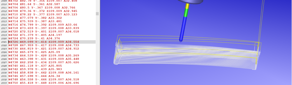
i used to work with Topsolid software , and this rapid move used to be in one line

Thank you
-
On 5/1/2024 at 4:17 PM, #Rekd™ said:
To change these colours....when in Verify go to File - Options - Graphics and make your changes.
Thank you
the problem is solved
-
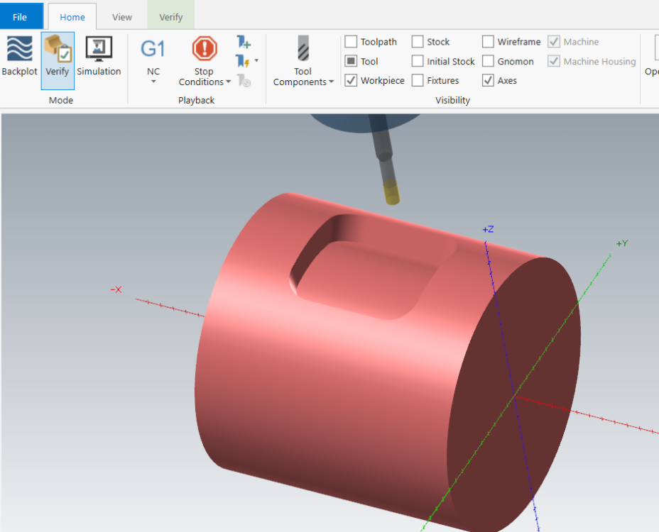
Hi
i have a problem with simulation , the work piece has the same color of stock.
please how to solve this issue.
-
8 minutes ago, AHarrison1 said:
I am currently using both for 2020 and have no issues opening solidworks files.
Are you refering to Mastercam stand alone version or MCFSW(MasterCam For SolidWorks)?
hi
i am referring to mastercam for solidworks v 2020 and its compatibility with solidworks 2020
-
Hi
we have solidworks 2020 in our shop. we want to get mastercam 2020 for solidworks . but it is marked that it is compatible with solidworks 2010------2019.
should we look for later version of mastercam for solidworks???
thanks for help
-
34 minutes ago, #Rekd™ said:
If you geometry is already rolled you don't need to unroll it first to use Axis substitution.
Attaching a Mastercam file is the best way to get help.
unroll geometrie to machine with 2d toolpath.
sorry for not being able to attach the file.
-
28 minutes ago, crazy^millman said:
That is unrolled correctly. You don't have a connecting shape to complete the rectangle. In the videos you have seen for other software they do a little behind the scene magic to close the shape you don't see. You have 2 Vertical lines and you can now draw to horizontal lines to close them and make a rectangle. I wouldn't do that mind you I would extend them to overlap each other that way when the toolpath wraps around the part I get a nice overlap verse a lip being left. that is the other thing they didn't show you in those videos is work they do to make sure that doesn't happen. The reference of using Multiaxis is not a dig on the software, but a process method to use the software to it's full potential. If your company didn't purchase the multiaxis then that is fine and you can use what you got, but to think there is an easy button like shown in some videos when in reality there is not I am sorry it is not that way. To make good toolpaths that really do a good job you sometimes have to do a little sweat equity. Then you get great toolpaths that does good work.
I have seen plenty of canned demos and the time I throw a real world part at most them and say okay 5 minutes just like you did in the canned demo every single time in every software they fail. You have a sample file you put some work into that you can share then someone will be glad to help, but I will not program your part for you other might be willing to. I offer programming services how I feed my family and would be glad to quote you programming that part.
thanks for responding,
what i cant understand is how yhe unroll function work .in solidworks i make a surface and a little gap and use the sheet metal to fold unfold gometrie.
in mastercam , this example i cant understand why the geometrie is not included in a rectangle (think about a piece of sheet and roll it above a cylinder).
sorry but i feel very confused
-
12 minutes ago, Greg_J said:
Do you have Multiaxis? If so I would use the Curve 5 Axis tool path.
i have seen video using the unroll and the 2d machinning (using other software) for roughing specially,why not doing this with mastercam .if only i can unroll the geometry the right way in a rectangular shape which contain all geometrie.
thanks for your response
-
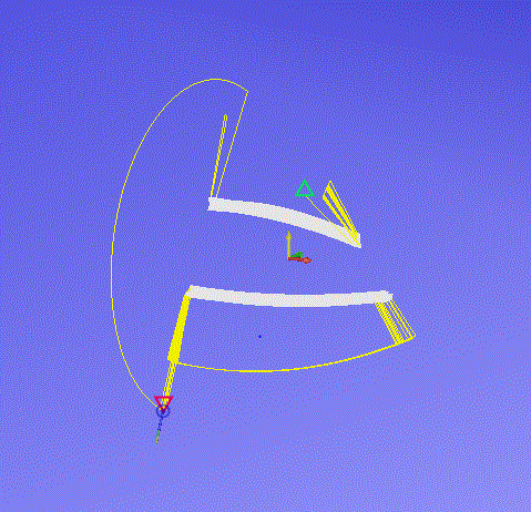
Hi
in order to machine this kind of pieces , i thaught to unroll the geometry and machine it with 2d tool path , then roll toolpath .but when trying to unroll i dont get a good sketch .
why dont have the unrolled sketch into a rectangle, so i can machine it like poket.
please have a look at pictures , and thanks for help

-
15 minutes ago, 5th Axis CGI said:
Don't let me or other scare you off. Are you in a Country where your only allowed certain freedoms to share things? If so then share what you can and we will try to help you as best we can, but understand if it gets to a point of crossing the education side of things help might be harder to give.
thank you . i think i should begin with buying the The Mastercam 2020 Multiaxis Professional Courseware .and have Mastercam 2020 Home Learning Edition/Demo Software.
Multiaxis is included, but most Add-Ons are not included or supported. what does this means
thanks for advise
-
3 hours ago, zachlancy said:
Please post your social, date of birth, favorite color, hasp number, and shoe size.
name anes
date of birth 5/4/1997
color blue
shoe size 42
hasp number ----------------
i think things turned into the wrong side.
thanks to 5th axis cgl for his contribution .
i apologize for participating in this forum.
-
5 minutes ago, #Rekd™ said:
The best way to get help on this is to post a valid Mastercam file instead of photos.
sorry i cant bring files at home . its is forbidden at school. i photo them with my phone.
and also i like doing it enough wrong ways to have a way to get it done.
-
4 minutes ago, 5th Axis CGI said:
Can't pay attention to that. You need to run a machine simulation and see what they shows. When you start dealing with rolling and unrolling Mastercam back plot or even display if back plot gives you the correct representation of motion. Where either running it on the machine or using a machine simulation/verification is the best method to see real world application of the work. Like you quoted done enough wrong ways to know this much and sometime this is where the rubber has to meet to road and just go do it and see what happens.
One last question ,can i make transphorm toolpath with a rolled geometry toolpath.
i noticed i have the same A value for each pattern.
thank you again and again
-
On 10/12/2019 at 6:16 PM, 5th Axis CGI said:
but to say I have done it enough wrong ways to have a way to get it done.
thank you alot for your help . i think using the 2d area mill with tapered angle and air region and then enrolling geometry is a good way as i can work with rest roughing.
for finishing i used a multy axis toolpath
i have worked in one teeth and i see that roughing and finishing dont match . please have a look at the picture
how can i fix this .
-
30 minutes ago, 5th Axis CGI said:
Wow your company paid to get Blade Expert then you should reach out to Aaron at CNC Software he loves these kind of challenges. Once I can confirm your company I will be glad to assist, but if your company can afford Blade Expert they can afford to call the dealer and have them get Aaron involved. I know I am the meanest person the forum and sorry if I come across that way, but please prove me wrong by providing some information about your company and I will eat my words.
i am a student . no company yet .i am just asking help for person who whant to help.
-
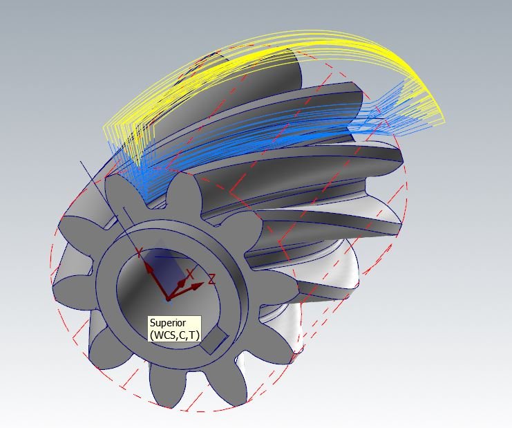
I was trying to rough a helical gear to machine in a 4 axis vmc.
i have no problem with finishing using morph between two curves or flow or parallel.
i tried to rough with multi axis rough but it seems to be a 5 axis strategy [not supported with 4 axis machine]
i tried to rough with blade expert like in the picture ,and when i try to run streaming simulation i got 'current tool path is not for 4 axis machine'.
which strategy should i use to rough this part .
-
WHY IN MASTERCAM THERE IS NOT ANY LATHE MACHINE SIMULATION ENVIRONMENT FOR LIVE STREAM LIKE OTHERS CAM SOFTWARE;
IS IT POSSIBLE TO BUILD A CY LATHE MACHINE FOR SIMULATION,?
THANKS FOR YOUR HELP
-
hi
my question is about programming sub spindle in mstercam.we have a machine with two spindle nd one turret . should i use the c y toolpath or mill turn .what is the difference ; and how can i train for this
-
5 hours ago, #Rekd™ said:
This does not seem like a educational user question.
Sorry. the machine we use is a 4 axis with the chuck in the right side .however in mastercam it is in the opposite side . i want to have a good simulation for my project.
sorry to bother you
-
i want to edit machine simulation 5 (2-4AXGEN VMCTA) and change the position of the 4axis chuck from left to right ;HOW CAN I DO THIS??
thank you in advance
-
14 hours ago, JParis said:
Ron summed it up nicely
I have a fairly complex part running on our HMC.....along the edges it's .035" thick +/-.001....
I cut them complete caged in the stock using tabs....we've run over 25k using this process....part loss is near 0%
That thin, it's ALL about process
what is the thikness of tabs ; how much tabs ; and how to clean them after machinnig
-
1 hour ago, JParis said:
Vacuum chucks/fixtures....
Sometimes if a part isn't complex, I'll use thicker stock and then a thin saw to cut off the part.... a little backside cleanup & done
In a pinch, double sided tape....I have also used heat activated glue sheets
It depends what needs to be machined
is there vices that can maintain 1 or 2 mm without domaging the pieces
-
hi
how to maintain pieces with little thikness (3MM 4 MM) to machine ;is there special vices?? we use to machine aluminium and pom C
an other problem occurs after dismantling the piece (pom c) from the vice ;we dont find the same measurment . how can this happen? and how to avoid this.
is using the scotsh brite a solution?


Mastercam Vericut Interface
in Industrial Forum
Posted
Do you have an idea how to fix this issue : when running vericut from mastercam interface i get this message : failed to initialize licencing
thanks