


RICARDO_GOMES
-
Posts
13 -
Joined
-
Last visited
Content Type
Profiles
Forums
Downloads
Store
eMastercam Wiki
Blogs
Gallery
Events
Posts posted by RICARDO_GOMES
-
-
6 hours ago, So not a Guru said:
Ok, I was just pointing out that it wasn't necessary, in this case. It was not meant in a derogatory manner.
I absolutely agree that you should be able to use all of your machines capability. That being said, I generally use 3+2, over 5X, unless I have a specific need for 5X (such as 5X being a faster solution).
Thank you for the final point you made at this reply, maybe you should have started by that in the previous answer.
When we use 5 axis continuos we low down the probability of having to use specific tooling to achieve a countour, for example. Time, G0 moves, tool changes, precision, M5 avoidances, etc, are all avoided if we can make the machine work as we need and not as easy to program at first glance as it can be.
-
17 hours ago, So not a Guru said:
Why does this need to be 5X?
Why not? If the machine can do it i need to know how.
-
 1
1
-
-
32 minutes ago, 5th Axis CGI said:
I reviewed the file more and you will have to use a Swarf Toolpath to cut that surface, but need to pay close attention to the Kinematics and closeness of the part to your work holding. I see a possible crash coming.

I will try it again with swarf, thank you.
-
26 minutes ago, 5th Axis CGI said:
Unless the post you have is setup to use a BASE WCS then you haven't gone about creating your WCS correctly, your WCS is where you will be creating your Work Offset on the machine at. I guess you could go about setting up a Work Offset like that on a 5 Axis machine, but not something just starting would normally attempt. I have been doing this for 30 years and not how I was go about creating my workoffset position on the machine. Then your C and T-Planes would use the plane you created. Now depending on the machine and control you will get a mapped position from your Workoffset for the machine you want (WCS) to your machining plane (C-T Plane) in your posted NC code and good to go.
First of all, thank you.
Yes, you are correct, i normaly use WCS at a fixed and straigth position, but in this scenario i don´t even know how to look at it and i am making it more confusing than probably should be...
However, even with correct WCS and planes, i can´t find a toolpath doing the profile aroud the tubular part without a crash, as you can see at your picture, that is the kind of stuff i also get. Wich one did you use to do that?
At my original file i have a 3D with 2 contour toolpaths, and one fixed 5th axe. I do not want that, i want only one pass, 5 axis continuos and where i can control the sides not allowing the tool going down touching the table. Is it possible? What toolpath should i use?
Thank you all for the responses.
Best regards
-
42 minutes ago, nickbe10 said:
Just out of curiosity, how did you end up so far out of your depth? Is this for work or college?
We will need to know a lot more, like what machine etc.
Regular stuff at the company i work for but done by 3 progamators, none of them will be at company next 2 weeks so i will have to do the jobs that come in. This one of those jobs.
-
Hi there folks!
I´m new to 5 axis machining and i need to get a part done using a 5 axis machine. I can do it without the 5 axis simultanesly working but i wanted to learn how to do it. I´ve tried several 5 axis strategies but i do not know how to control the tool, for example, it goes down at the table...
Please, note the part atached. To machine that surface using 4 axis or even 5, wich toolpath can one use? Thanks.
Mastercam 2017
Best regards!
-
17 hours ago, RLeuschen said:
From the calculations i did real quick, The feeds are close to a machine running non cylindrical/polar tool paths (g107/g112..etc) on a 26.054 diameter part.
When we have operators question the feed rates on our lathes during a milling operation, we use the attached pdf to give a general idea of how the post calculates the correct feed to match ipm/diameter/..etc.
If the machine does use a cylindrical/polar tool path, then the f1000. that you have programmed would be seen as f1000.
Hope this helps some.
Thank you.
However, feeds for rotary paths are never posted on a knowledgeably way . Today i have found the arc filter/tolerance afecting it all the way. Problem is, i never know the values that will be posted and have to try tenths of times to adjust all the tool feeds and arc filter/tolerance until it gets aceptable values. It should exist a easyear way to do this.
-
Hi,
does any one know why feed does not come out correct as tool defined after post processing?See atached photos, please. How can i correct that? Thank you.Aditional info: fanuc control, vertical miling center with rotary 4th axe. -
Hi!
I am from Portugal.
I work with CNC machines since 2008.
I am new to mastercam, never had to use it before.
I hope to find some answers and Share wathever i can.
Best regards
Ricardo
-
Can not open it because i am using mc2017 and you are using a newer version.
Did you try to create a new plane at the engraving curve instead of using top plane? Create a new surface if you do not have it and create a new plane in there, at the curve or create a new curve on edge at that new surface.
-
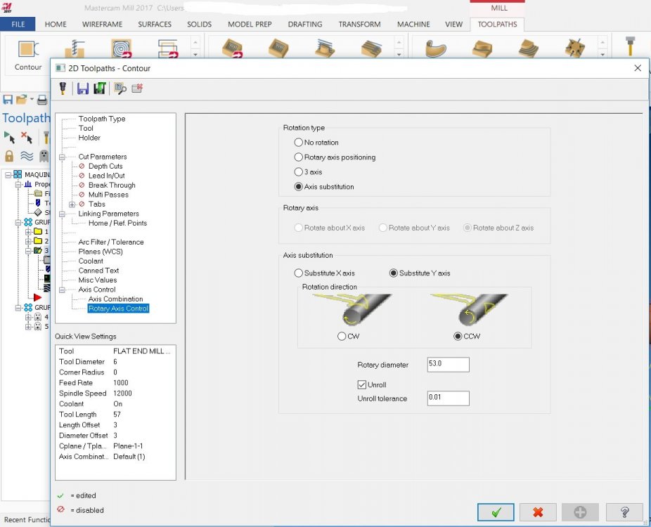
Well, no one had a clue but i finally made it.
I have used a 3D contour but it needed to be changed at some points: the use of axis substitution, y axis. And this Y axis take me a lot of time to find out. Last, use a rotary diameter bigger than the part itself to achieve side by side perfect tool alignment. That is it.
-
 1
1
-
1
-
-
Hi folks,
I am a new member at the forum!
I,ve started working with mastercam a few months ago and i have never had any kind of formation at it, so, i am learning it by myself, with the reasonable doubts that are comming.
Well, see the atchment, please, it is a part i have to machine on a vertical milling cnc center. The machine have XYZ plus A axis, A is a rotary axis.
The part is a conical part with a recess at the outside. I have tryed a lot of diferent configurations but i could not have success wit any one. It absolutly needs the sides to be sharp edges, not round ones. How can i achive that? As you can see, i use a 5 axis flow to achive the recess, but i can not find a way to achive the sides to be sharped edges. What do you advise?
Thanks in advance.
Best regards!
-
1
-

VMC 5 axis toolpath
in Industrial Forum
Posted
Why are you assuming i have started working today?
This is simple: any one asks for help, i will help if i can. I will not be a smart xxxx over someone because i know how to help and laugh about it. If i do not know how to help i will not answer or i will search to also learn and after can answer. That is how i do 5 axis on mastercam without even having a simple qualification on it. Thank you. Best regards.