


average_jonny
-
Posts
6 -
Joined
-
Last visited
Content Type
Profiles
Forums
Downloads
Store
eMastercam Wiki
Blogs
Gallery
Events
Posts posted by average_jonny
-
-
On 11/29/2019 at 3:56 PM, Rich Thomas 4D Engineering said:
My Turn! I read many years ago about using a "tool boundary" perpendicular to the cutting direction with Surface Finish Contour. It helps maintain a constant stepover relative to the chain, a bit like Scallop or Flowline. Take a look at the attached file and look at the containment boundary I used.
Big thanks Rich, this looks very tidy and to be seems to be the less convoluted way.
On 11/30/2019 at 10:05 PM, jlw™ said:I've never seen this. Having said that, if you completely remove the containment you get basically the same path. I don't see what this containment is doing. I'm going to have to play with this one more.
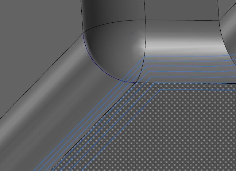
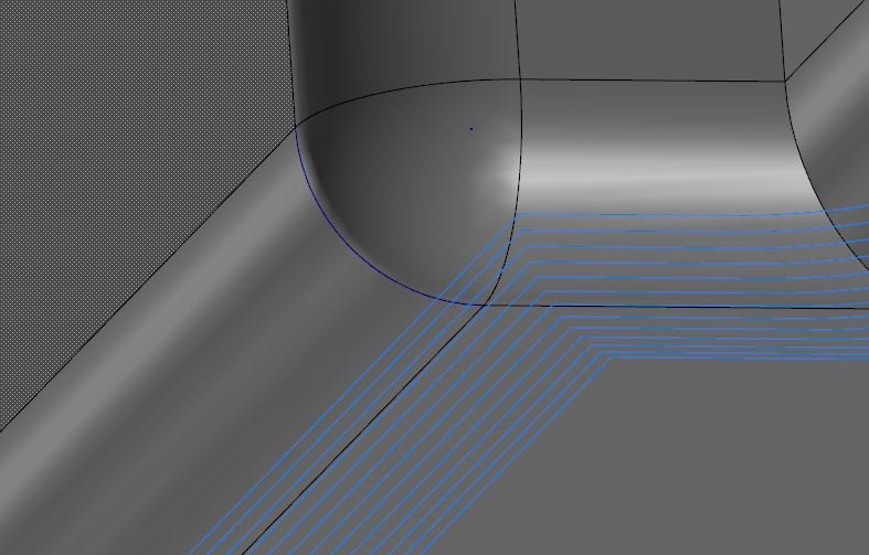
Without the containment boundary the stepover towards to the bottom of the fillet becomes exponentially larger, with the boundary it has the reverse effect. Attached two captures of with and without to show this.
-
 2
2
-
-
3 hours ago, David Colin said:
You should try Morph toolpath if you have it
Thanks guys, but could you possibly upload this again as a.zip as my work computer doesn't have a .rar extractor.
-
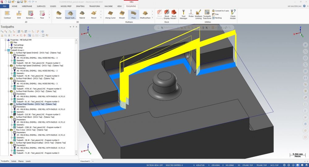
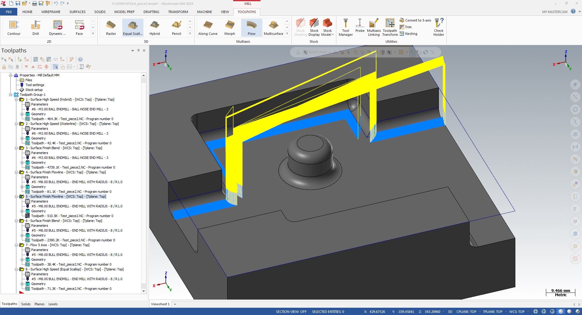
So I come from a Powermill background but my current place uses Mastecam which I've been self learning over the past five weeks. One thing I can't seem to get working and no one at my place has any new ideas, is machining a fillet without a form tool, or a tool smaller than the fillet itself. In Powermill there was a toolpath called 'Optimised constant Z' , which is equivalent to Mastercams waterline, however OCZ would maintain an equal stepover even as the geometry angle changes. The closest toolpath I've found is flowline however it breaks the toolpath at some corners as seen in the attached capture, I've also attached the file so you can see for yourselves.
Any ideas on the best way to go about this?
-
13 hours ago, billb said:
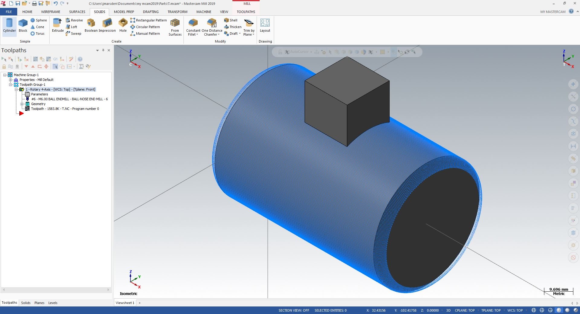
Thanks for whittling this down to a simple case. I created a similar part and duplicated the problem in X9 thru MC2020. I logged it as D-39692. If you backplot (and especially if you enable display of endpoints) you will see that the tool machines along the cylinder right up to the block but then keeps down thru the block. So I think this is a “retract” issue (tool not lifting when it should).
I didn’t find any work-around yet.
Thank you for letting us know about this.Thanks for doing this Bill, look forward to seeing what comes next with it. Also just to add on, when the cut pattern is switched to axial why does it start at a 90 degree angle from the toolpaths plane? Normally I could get around this by telling it to start at -90 or +90 but the values are limited from 0 - 360.
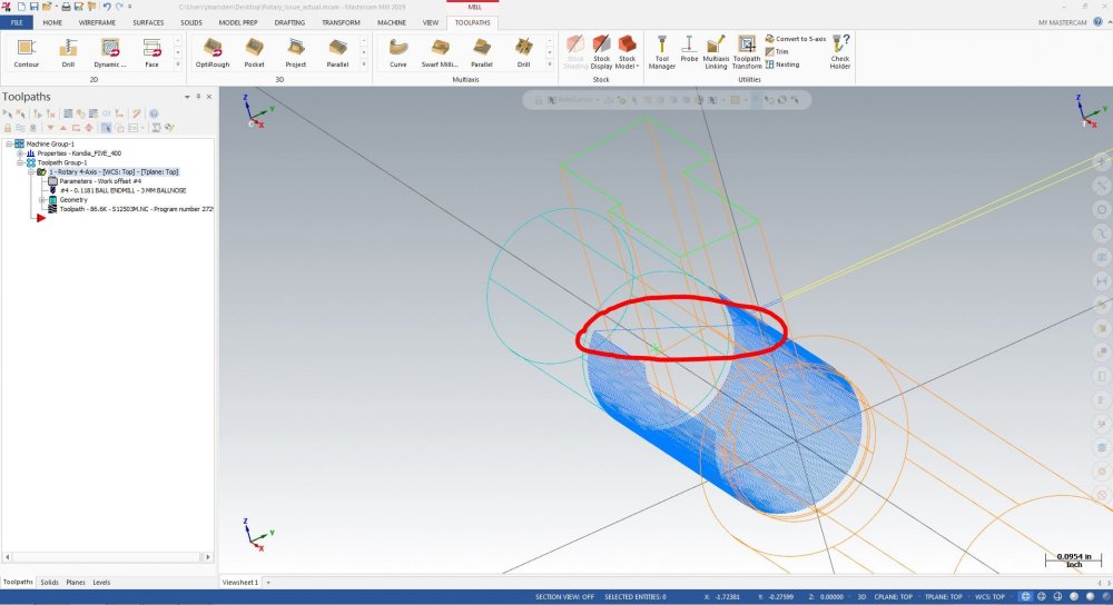
In the mean time I've attached the file from the original post as well as the actual file in which I first encountered the issue (although I've deleted the rest of the toolpaths and just kept the rotary 4-axis one). You can see in this file and the attached capture that it does detect some geometry but as Bill said doesn't retract and gouges straight through collision check surfaces.
-
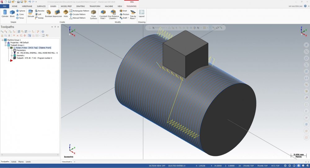
Just came across a strange issue, potentially a bug, when using the rotary 4-axis toolpath. I've recreated the issue using a simple cylinder and a block which isn't too dissimilar from the actual geometry.
So to put it simply - when the cylinder is selected as the surface cut pattern and the block is selected as the collision control and the cutting method is set to rotary cut the toolpath generates as expected and it avoids the block as seen in the attached capture.
Now if you set cutting method to axial cut with the cut pattern and collision control surfaces still the same the toolpath does not detect the collision geometry, as seen in the other attached capture.
Any ideas why this is happening? Running Mastercam 2019 BTW


Toolpath for machining a fillet without a form tool?
in Industrial Forum
Posted
Flowline likes to do funky things in internal corners...