


kwolf
-
Posts
390 -
Joined
-
Last visited
Content Type
Profiles
Forums
Downloads
Store
eMastercam Wiki
Blogs
Gallery
Events
Posts posted by kwolf
-
-
Oh 5.4?
I think you have to upgrade Vericut to 6.1.2+ then.
-
Check the CGTech forum first.
I know they updated c-hook and fixed some bugs for mastercam and bunch of CAM packages interfaces after releasing v6.1.2
http://www.cgtech.com/forum/viewtopic.php?...mastercam#p2888
-
Not recently been wishing this feature for a long time for Mastercam. Long time user of Mastercam v7.2 and PowerMILL v2.5 , maybe 8-9 years ago

-
- Separating calculation of the toolpath and link & lead moves.
So a new command to apply link moves (broken/follow surface/..) between toolpath passes without re-calculating the operations.
And yet better, ability to change each link move to another type ,eg, you may want to change from broken to follow surface in some parts of the toolpath.
All without re-calculation the entire toolpath of course.
-
quote:If create boundary is running to slowly you might try loosening the tolerance on it a bit, it should speed up.
I encountered another problem with concave fillet surfaces, according to MC help, the boundary should be smaller for concave surfaces. But the generated boundary totally overlaps the fillet.

Although all surface orientations are good the boundary is not what it should be.
Can anyone try one of the concave fillets in the sample file "LEFTOVER 3D COLLAPSE-MM" and verify this? Maybe I'm missing something.
TIA
@mchin-pilot
Just what peon said, in PowerMILL.
-
You da man.

Is it a new c-hook? I haven't touched MC since v9.
It's almost what I wanted. Far better than manually create/select job.

However it's too slow and in one case I had to shutdown MC. The CPU usage was 100% for 5 min when computing on a simple rhino sweep surface.
Great tool, hope newer versions have better response time.
-
Hi people,
I want to know whether there's a way in X3 to calculate and find real tool containment boundary of selected drive surfaces with respect to the
- tool shape/size
- tolerance of calculation
- thickness on drive surfaces
We do this to find tool containment in another CAM package.
I don't know how to post a picture but a simple example would clarify the situation.
If I'm using a 10mm diameter ball nosed and want to machine a 4 mm radius concave fillet there's no boundary for machining.
Obviously the result is different if a convex fillet is used, this time the boundary may totally overlaps the fillet.
As with this new boundary, the tool machines the very selected surfaces, there's no need to select any check surfaces.
Is there any c-hook or workaround to get the real containment tool boundary?
Thanks and glad to be here again
-
DELCAM cad model which is basically Bezier surface model.
-
Did you check (model) the surfaces? Probably there's something wrong with them, like a self intersecting surface or alike.
-
Hi Jimmy,
Yes 9 pin on PC.
-
Hi,
Does anyone know what are the configurations for connecting PC to Acramatic Vickers 2100 controller, Cincinnati Milling machine? Protocol/Baudrate/Parity/Cable config/delay/special header on the file ..
I made the cable as shown on the manual and set 9600 baud rate and tried changing everything I could imagine(parity/stopbit/xon_off) on both ends but couldn't succeed.

Uploading to controller:
The best I got when send file from PC to controller is, PC shows sending file but nothing appears on controller.
Downloading from controller:
I had to cancel sending file from controller to PC as well since nothing happened on the ends.

Thanks in advance
P.S. Using CIMCO for data transfer.
-
Good Morning Iskander,
Thanks for the quick reply.
What I really want to know is , is it bug? We use to do the same thing , using boundary limit or leaving a real small amount on check surfaces in Cimatron-E or other workarounds that you know better than me. What bothers me now is if we have to see this in MC too.
I might be wrong but I don't think the same behavior would exist in previous versions. -
Just uploaded the file "VERTICAL WALL.MC9" to the FTP area.
A cylinder(solid) is used as check surface(s), why the tool in 1st OP comes up and down between each pass,even 6 times up/down, and keeps its contact with the cylinder? I think in the previous versions it would be avoided and the tool would be kept down on the flat drive surface.
In the 2nd operation, the cylinder face has been drafted 5 degrees and the moves between each pass are what really expected.
Is there a bug in mesh generation? We saw something like this in Cimatron-E whenever there's a vertical wall.
MR0904
-
Sorry to hijack the topic.
As an amateur software programmer in old days I'm really interested in how some CAD/CAM systems can do this.
Please let's know if you have something in your mind. I think the best way is to use an integrated CAD/CAM. The CAD-side can generate tolerances for each face and trasfer it to CAM side, the user can then use those numbers in "stock to leave" parameter. So there's no need to rebuild or recreate geometries. Maybe for XI.

This method can be used for simple geometries especially for analytic geo now.
-
quote:There is a software package we are investigating that will alter the Pro/E model to make it to the mean ...
Very interesting, sometimes changing a value by very very tiny amount can cause a feature to fail in a solid modeler. I wonder how this program will interpret such tolerances, prolly it should rebuild all the features again, this means it should work as a PTC plugin.
I saw a demo by TopSolid years ago and the guy told us the CAM side can machine the geometry created by CAD side with median tolerance.
-
quote:Soon, SW and MC will be fully intgrated. I predict that DSS systems (Solidworks) will buy-out CNC Software(MasterCam). resistance is futile.
Interesting. Where did you get the info?
-
AMD Athlon XP1800+
1GB RAM
GeForce 3 Ti200 128MB
7200rpm Maxtor
1st time - 55
2nd time - 22
-
Sorry I didn't notice about SAT Code.
New Parasolid file "T24018-KWOLF.zip" was uploaded. Please check to see if no solid body is missing.
HTH
-
DavidB,
Try this:
- Import Parasolid: File->Converters->Parasolid->Read File
- Save it as ACIS(SAT): File->Converters->SAT->Write File->AllSolids
- File->New
- Import SAT: File->Converters->SAT->Read File
(you get many parasolid errors ), too few parents or disjoint shells, just click OK as many times as it appears
- Check to see if all bodies are present
- Now save MC9
I could help more if I had all the programs I need. We just installed the OS on this machine and the only CAD/CAM here is MC.
Probably parasolid contains some cosmetic threads or fancy features. That's why you get those errors.
HTH
-
AFAIK PTC uses Granite as its kernel but it can export Parasolid/ACIS in new versions too.
Maybe decreasing model accuracy in WildFire can output a better Parasolid export.
-
Thanks for the replies,
We just made it. Uninstalling windows was the solution. So we're almost sure that a driver prevented it from hibernation.
Now SiSoft Sandra shows this
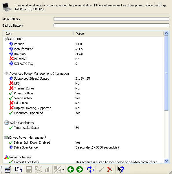
-
Bullines, we ran Sisoft Sandra and here's part of the report about APM/ACPI.
There's an S5 in front of Supported S(leep) States. Is that what you wanted to know?
Besides it says Hibernate not supported.
long ago it could.
-
I can change to max/min saving and disabled.
If I change it to max saving it just reduces suspend mode or hdd power down time. I didn't notice any other change.
I flashed latest BIOS (1017) for this mobo.
-
What is a programmer?
in Industrial Forum
Posted
Being a modeler (surface/solid) helps alot too. I mean understanding 3d geometries and how to create them sometimes helps to choose better strategies in machining especially when