Coco
-
Posts
36 -
Joined
-
Last visited
Content Type
Profiles
Forums
Downloads
Store
eMastercam Wiki
Blogs
Gallery
Events
Everything posted by Coco
-
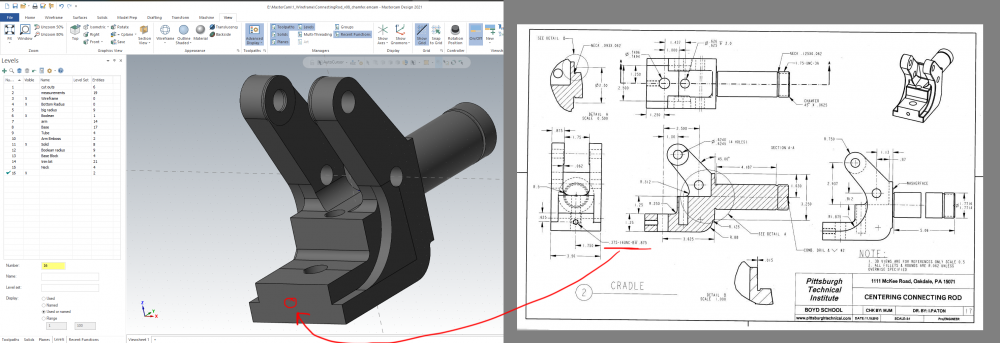
Found the two bottom edges, you mentioned. I updated the model. Thank you so much for all your help, Crazy^Millman.

-
Thanks for keeping me honest, crazy^millman. Here is the fix.
-
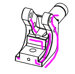
You mean these edges?
-
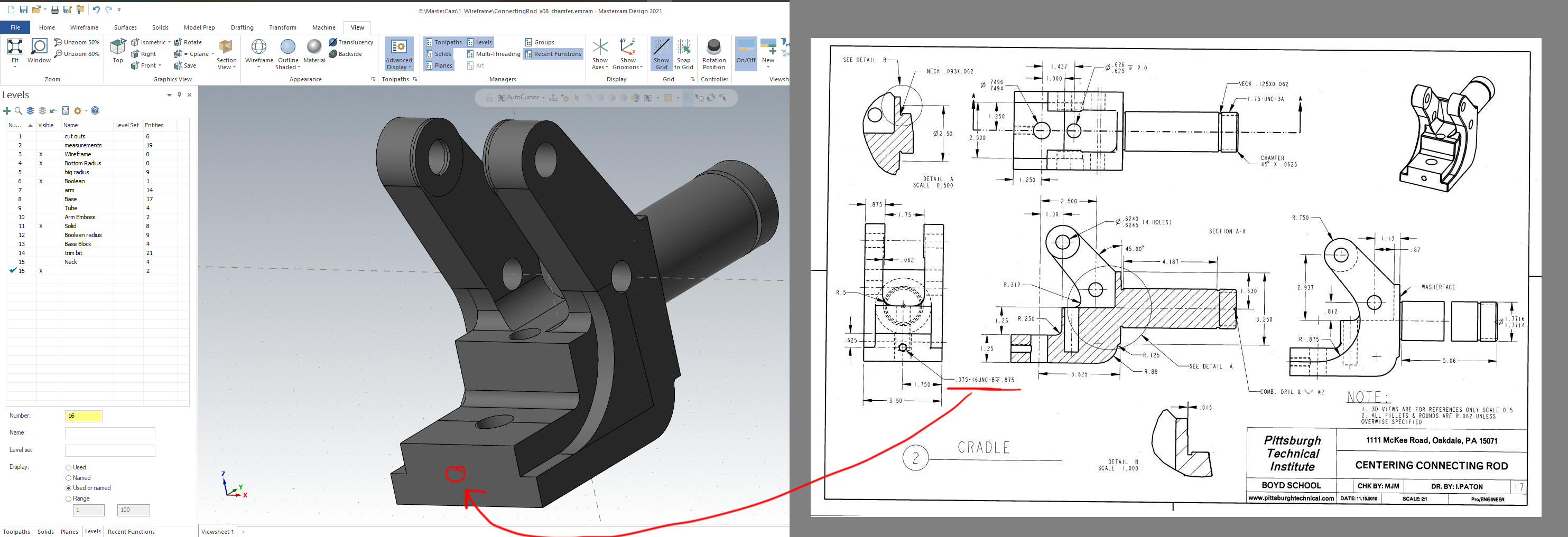
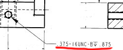
The demo of Mastercam does not do tool paths. So I just punched a hole with a diameter of .375 and a depth of 0.875. Thank you for all your help "Crazy^millman", "So not a Guru", and "Rekd." I learned a lot. Any suggestions on a new free blueprint to model and learn more? Cheers,

-
So not a Guru, thank you for the tip, "The .375-16UNC callout is the SAE thread size in diameter & threads per inch the .875 following the depth symbol is the depth that the hole is tapped to." I'm going to start learning that, today.
-
Thank you, Rekd and Crazy^millman. I hope to get the Solid work done, by tomorrow. Thank you all for helping understand this blue print. Gotta find another challenging blueprint after this one.
-
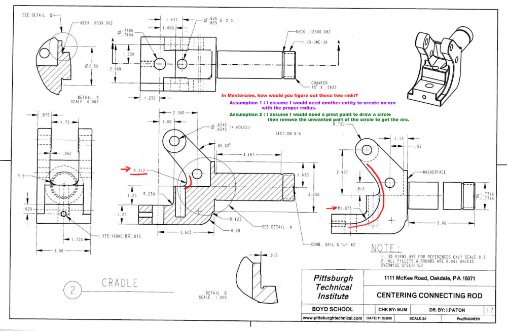
Thank you, now I'll try to understand your explanation of R .312. Thank you, again.
-
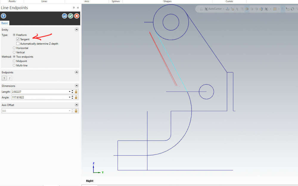
I just drew a tangent line connecting the two entities. Is this correct? The drawing looks like there is a slight arc where they meet in the middle. I used a lline.
-
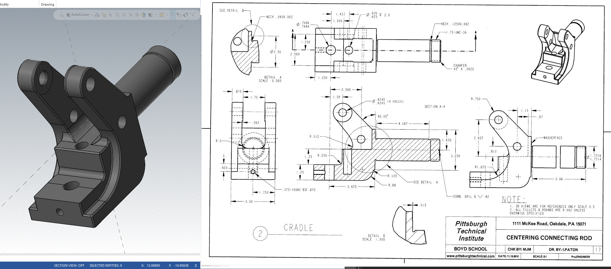
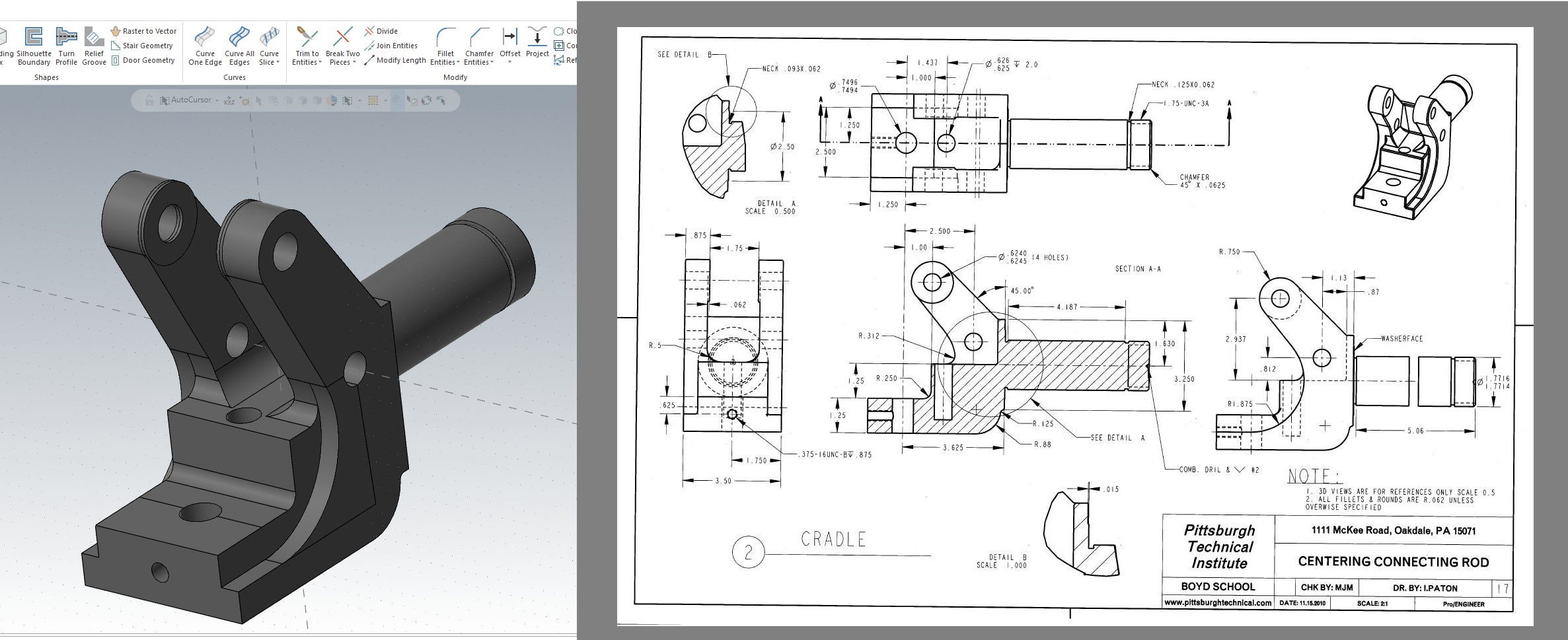
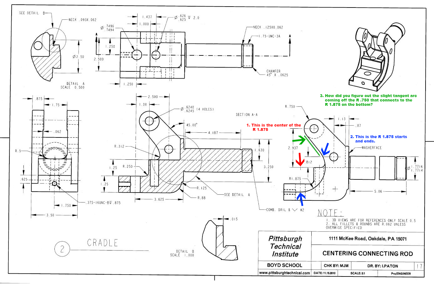
I'm try to understand how the bottom R 1.875 connects to the top R .750. 1. Thank you for explaining how to find the center of the R 1.875. 2. I now see where the R 1.875 starts and ends. 3. How did you figure out the slight tangent arc coming off the R .750 that connects to the R 1.875 on the bottom? Thank you again for helping me understand this blueprint.

-
Thank you, Crazy^millman. I'm a newby, Thank you so much for helping a "stranger" understand how to interpret this blue print. May the divine light shine on you, always.
-
Good Lord, that was an intense 10th grade machine shop class.
-
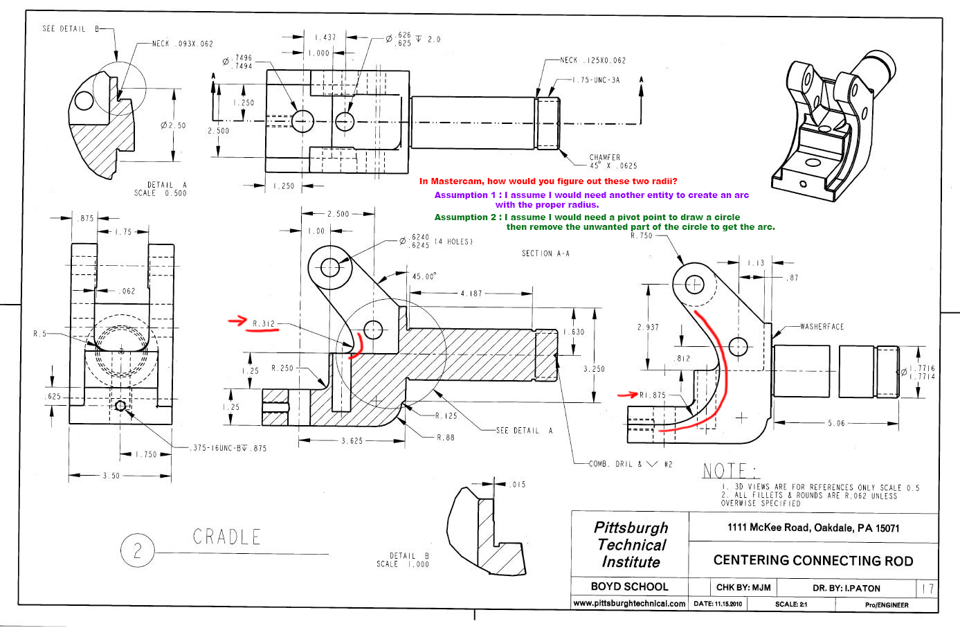
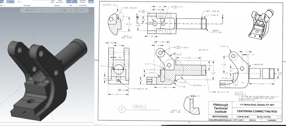
In Mastercam, how would I figure out these two radii? I had two assumptions that did not seem to work out. Assumption 1 : I assume I would need another entity to create an arc with the proper radius. Assumption 2 : I assume I would need a pivot point to draw a circle then remove the unwanted part of the circle to get the arc. I'm learning as I throw myself into this blueprint I found on the internet. Thank you all for your help.
-
I don't quit understand yet, but I'm going to learn about thread size and diameter. Thank you "So not a Guru." This blueprint it leading me into new territory. Ha ha.
-
I just now understood what you wrote, Crazy^millman. Thank you, so much. That took a long time to sink into my head. You wrote it so well, I don't know why it took me so long understand. Many thanks to you. Cheers,
-
On the internet, where would I go to learn how to interpret these annotations. I don't even know the vocabulary for these annotations. Cheers,
-
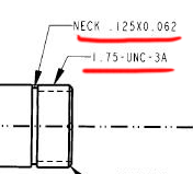
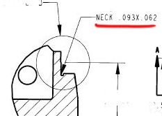
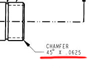
I'm new to blueprints, 1. I don't understand the "Neck.125X0 .062" and how that relates to the basic math. Neck .125X0 .062 is very strange to me. I would love to know more about this. 2. "Neck ..093X .062" is also very strange. I would love to understand this. Is there a web site that converts these measurements into metric easy to understand layman language? Thank you Zeke, for circling the measurements in question.
-
Hello, crazy^millman. I'm trying to learn. I see where you got the measurement of "5.06." But where did you get the information in the drawing to do basic math? In other words, I do not see where you gathered the information in the drawing. "5.06+.093=5.153 gives you the distance from the Shoulder to the end of the part. Detail A define the Groove against the should .093 Wide by .062 deep per side or .125 diametrically. The other one is 4.187 + .093 from the shoulder and it .125 wide x .062 deep per side or .125 diametrically." I appreciate your help,
-
Awesome! Thank you, I did not know there was right click customization feature. Cheers,
-
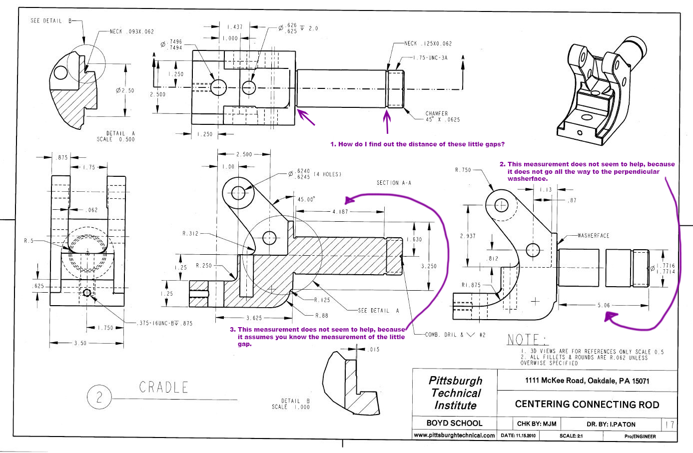
Hello, I am trying to learn how to read blueprints. 1. I am trying to figure out the measurements of the little gaps on the neck. 2. The "5.06" measurement does not go all the way to the perpendicular washerface wall. 3. The 4.187 measurement assumes you know the distance of the little gap.


-
Thank you, nickbe and Thee Byte. I now see the "Analyse Distance" in the Home tab. Cheers, Sean
-
Thank you, gcode. "select the entity and hit F4" works. What if there is no entity...What if I want to measure the negative space between entities? Is there a tape measure of some kind?
-
In Mastercam 2021 demo, 1. Is there a way to measure the length of a line that is all ready drawn? 2. Is there a way to measure a radius of an arc? 3. Is there a way to measure the distance between two lines that have already been drawn?
-
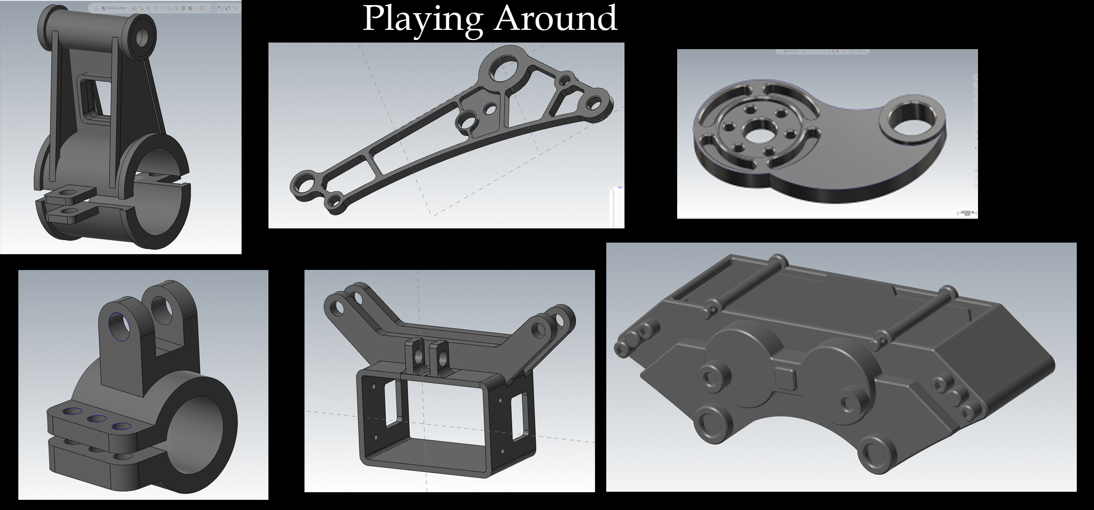
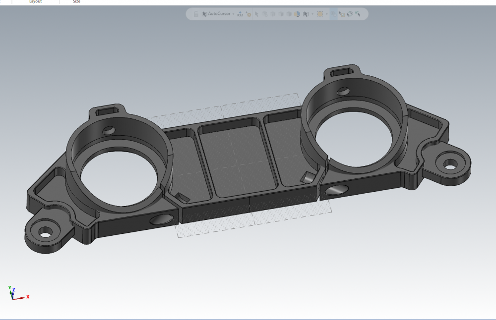
Hello Daniel, I have been playing around with Mastercam Demo for a couple weeks. This is what I have been doing. And this one

-
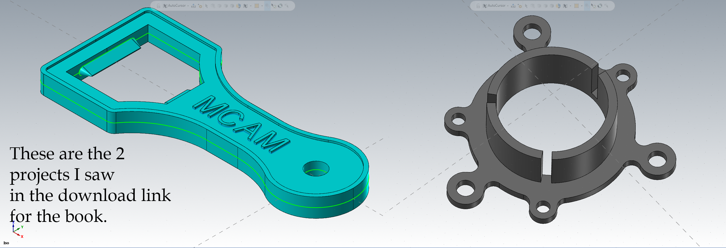
Hello AHarrison1, I have a question, there were 2 examples in that project download for the "Mastercam 2021 Solids training." Are those 2 projects the only projects in the Mastercam solids book?

-
In the "Store" is there a way to see pictures of the modeling projects in the "Mastercam 2021 Solids Training Tutorial" book? I just want to see "what kind of models" are being taught in the book. I'm not asking to see the tutorials, I know the actual tutorial can only be viewed if you buy the book.